Harman Kardon HK680I Owners Manual - Page 6
countries, owing, Safety, Agency, Electrical, requirements, these, receptacles, covered.
 |
View all Harman Kardon HK680I manuals
Add to My Manuals
Save this manual to your list of manuals |
Page 6 highlights
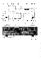
Connecting other equipment to the hk680i A pair of AUXILIARY INPUTS (45) is available at the rear of the hk680i for the connection of any "high level" output equipment. A special tuner for long wave, marine, aircraft or citizen's bands, etc., may be connected. Or you may choose to connect the output of the audio section of a television receiver. Any number of choices are available. Consult your audio dealer for information as to what equipment is compatible with your hk680i. Connecting speakers Use two-conductor stranded wire to connect your speakers to the receiver. Eighteen gauge lamp cord (zip cord) is satisfactory, but a heavier gauge (16 or 14 gauge) is preferable, especially for distances over 25 feet. Cut two segments of wire long enough to reach each speaker. Separate the conductors at each end of the wire segments for a length of two to three inches. Then carefully remove about one-quarter inch of insulation from each free end. Twist the strands of each conductor so they are smooth and tight with no loose strands. Lamp cord usually provides a "code" that differentiates the two conductors. A conductor may be coded by a rib, sharp corner, or indentations molded along the length of the insulation. In some cases, a thin colored thread is molded inside the insulation of each conductor. In others, one conductor is darker than the other, or the insulation of each conductor is of a different color. Connect the bare ends of one segment of lamp cord to your right speaker as follows: Connect the coded conductor to the speaker's positive ("+") terminal, and the uncoded conductor to negative ("-"). The "+" and "-" markings are in general use, although some speakers use other labeling systems, such as "1" and "2," "A" and "B" and so on. Find the appropriate row of speaker connectors on the receiver marked SPEAKER SYSTEM 1 (50). Push in on the red plastic head of the connector marked RIGHT to reveal an opening beneath. Insert the bare end of the coded conductor into the opening. Release the connector. The conductor should now be locked firmly into place. Insert the uncoded conductor into the adjacent black connector marked GND. Repeat the procedure for the left speaker, taking care to observe the coding of the conductors as described for the right speaker. If the code is followed as described, your speakers will be connected "in phase", which is important for solid bass and precise lateral location of the sound source. To connect a second pair of speakers, repeat the procedure for the right and left speakers of the second pair, using the receiver terminals marked SYSTEM 2 (51). Connecting an AM antenna A ferrite loopstick type AM ANTENNA (36) is provided and can be rotated to improve reception. If an external AM antenna is used, connect it to the terminal marked AM (41). Connecting FM antennas If no outdoor antenna is available, connect the lugs of the dipole (supplied with the unit) to the FM300O, BAL terminals (39) and (40). The dipole can then be tacked or taped to a wall or the back of a shelf. However, reception will be greatly improved if the receiver is connected to an outdoor FM antenna system. If you live in a fringe reception area, or if your house is situated among obstructions (such as mountains or tall buildings), you may need a more powerful, directional FM antenna. To connect 30052 (ohm) outdoor antenna wire, attach as described in the preceding paragraph. However, if your cable is 75 ohm, as is the case with many outdoor antennas, it will be round with either two protruding wires or a threaded coaxial connector. If the cable ends in bare wires, connect the wire that forms the outer mesh braid to the terminal marked FM 7511 UNBAL GND (38). Connect the solid, copper-colored wire protruding from the center of the cable to the FM 300Q BAL terminal (39). If your 75O, cable has a threaded coaxial connector, fasten it on to the threaded antenna receptacle (37). AC convenience outlets* Three AC outlets (52) on the rear panel of the hk680i provide power connections for turntables, tape decks or other equipment. One is marked UNSWITCHED and provides power whether the receiver is turned on or not. Those marked SWITCHED provide power only when the receiver is turned on. If you have completed the connections above, you are now ready to place the hk680i in its permanent position and plug the POWER LINE CORD (53) into an AC outlet. To turn the unit on and off, press the POWER switch (2). When power is on, the POWER indicator (1) will light. To operate your hk680i Speaker selection and headphones The SPEAKER 1 (4) and SPEAKER 2 (5) switches select the pair of speakers to be played. When either switch is depressed, the corresponding pair of speakers is activated. The front panel HEADPHONES jack (3) accepts headphones for personal listening. Headphones may be used simultaneously with speakers if desired. To play records Depress the PHONO pushbutton (15), activate your turntable, and advance the VOLUME control (26) clockwise to a comfortable level. If you hear a hum at average listening levels, turn the POWER switch (2) off and check to see that phono and ground connections are secure. *In some countries, owing to Safety Agency Electrical requirements, these AC receptacles are covered. 6
-
 1
1 -
 2
2 -
 3
3 -
 4
4 -
 5
5 -
 6
6 -
 7
7 -
 8
8
 |
 |