Harman Kardon SC18 Owners Manual - Page 4
Speaker, System
 |
View all Harman Kardon SC18 manuals
Add to My Manuals
Save this manual to your list of manuals |
Page 4 highlights
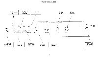
SPEAKER SYSTEM SELECTOR SWITCHES Your music system has been provided with 2 independent speaker selector switches. If your stereo music system is connected with 1 set of speakers (1 system), the system 1 speaker selector switch must be in the "ON" position. If you have 2 sets of speakers (2 systems), the system 1 and system 2 speaker selector switches must both be in the "ON" position for both systems to operate. Should you desire to listen to stereo-headphone alone, the speakers (either one or both systems) can be turned off at your discretion. SPEAKER G Q SYSTEM LEFT RIGHT SPEAKER SYSTEM 0 2 • C CONSULT l/k . t 4i L,'4', ` MOVING :-;) LEFT I RIGHT c:
-
 1
1 -
 2
2 -
 3
3 -
 4
4 -
 5
5 -
 6
6 -
 7
7 -
 8
8 -
 9
9 -
 10
10
 |
 |

SPEAKER
SYSTEM
SELECTOR
SWITCHES
Your
music
system
has
been
provided
with
2
independent
speaker
selector
switches.
If
your
stereo
music
system
is
connected
with
1
set
of
speakers
(1
system),
the
system
1
speaker
selector
switch
must
be
in
the
"ON"
position.
If
you
have
2
sets
of
speakers
(2
systems),
the
system
1
and
system
2
speaker
selector
switches
must
both
be
in
the
"ON"
position
for
both
systems
to
operate.
Should
you
desire
to
listen
to
stereo
-headphone
alone,
the
speakers
(either
one
or
both
systems)
can
be
turned
off at
your
discretion.
STEREO
-MONO
SELECTOR
SWITCH
This
unique
switch,
which
is
located
on
the
rear
panel
of
your
Music
System,
selects
SPEAKER
SYSTEM
2
output
for
stereo
or
monaural
operation.
If
you
desire
to
use
SPEAKER
SYSTEM
2
to
operate
monaurally
in
one
or
two
alternate
loca-
tions
(one
speaker
for
each
location)
place
this
switch
in
the
MONO
position.
When
operating
SPEAKER
SYSTEM
2
stereophonically
the
STEREO
-MONO
output
switch
must
be
placed
in
the
STEREO
position.
It
should
be
noted
that
the
STEREO
-
MONO
switch does
not
affect
the
normal
stereophonic
output
of
speaker
system
1.
CONNECTING
THE
SPEAKERS
FOR
STEREO
OPERATION
(1
SYSTEM)
The
cables
supplied
may
be
easily
dressed
around
the
molding
for
an
inconspicuous
and neat
installation.
Do
not
drive
the
staples
or
tacks
through
the
center
of
the
wire
for
this
may
short
out
the
two
sections
and
will
decrease
the
overall
volume
or
short
out
the
speakers
entirely.
1.
Plug
one
end
of
the
speaker
cable
into
the
receptacle
on
the
rear
of
your
left
speaker
(this
is
the
speaker
on
the
left
as
you
face
the
speakers.)
2.
Plug
the
other
end
of
the
speaker
cable
into
the
LEFT
speaker
receptacle
on
the
rear
of
the
system.
3.
Similarly
connect
the
other
speaker
cable
to
your
right
speaker.
4.
Attach
the
other
end
of
the
speaker
cable
to
the
receptacle
marked
RIGHT
on
the
rear
of
the
system.
5.
Your
music
system
is
now
connected
for
1
system
stereo
operation
and
is
operative
when
the
speaker
selector
switch
on
the
front
panel
is
in
the
speaker
System
1
"ON"
position.
CONNECTING
THE
SPEAKERS
FOR
STEREO
OPERATION
(2
SYSTEMS)
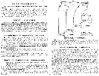
1.
Connect
all
4
speakers
for
your
two
system
operation
as
shown
in
the
diagram
below.
2.
To
operate
speaker
system
2
stereophonically
the
STEREO
-MONO
output
switch
located
on
the
rear
panel
must
be
placed
in
the
STEREO
position.
For
further
information
regarding
the
operation
features
of
this
switch
see
the
paragraph
STEREO
-MONO
SELECTOR
SWITCH.
3.
You
may
now
select
either
system
1,
system
1
and
2,
or
system
2
by
the
use
of
the
speaker
selector
switches
located
on
the
front
panel
of
your
Stereo
Music
System.
-2-
G
LEFT
RIGHT
0
SPEAKER
Q
SYSTEM
CONSULT
C
l/k
.t i
4L,
'
4
', `
MOVING
SPEAKER
SYSTEM
0
2
•
:-;)
LEFT
I
RIGHT
c:
<:,,vss5.,„
);
4.1
OPTIONAL
q
SPEAKER
I
(
CONNECTIONS
-ill
r
-r
r
,j
SYSTEM
2
0
SYSTEM
I
CONNECT
SPEAKERS
WITH
CARE-
AVOID
ACCIDENTAL
SHORTS
STEREO
HEADPHONE
RECEPTACLE
The
stereo
headphone
receptacle
located
on
the
front
panel
will
accept
any
headphone
with
any
impedance
rating.
The
headphone
receptacle
is
"ON"
at
all
times.
If
you
wish
to
listen
to
the
headphones
alone,
see
the
paragraph
"Speaker
System
Selector
Switches".
CONNECTING
THE
FM
ANTENNA
MODEL
SC1810
Due
to
the
exceptionally
high
sensitivity
of
your
system,
the
48"
wire
supplied
is
sufficient
for
all
but
the
most
difficult
locations.
The
balanced
antenna
input
is
designed
to
accept
a
300
12
antenna,
indoor
or
outdoor
type.
When
using
the
antenna
supplied
connect
one
end
of
the
48"
wire
to
either
of
the
FM
antenna
terminals.
Horizontal
placement
of
the
antenna
will
yield
optimum
recep-
tion.
The
antenna
may
be
tacked
to
the
back
of
the
molding
behind
the
equip-
ment
or
to
the
shelf
you
use.
As
FM
signals
are
in
the
same
broadcast
frequency
range
as
TV
signals,
they
are
affected
by
the
same
external
conditions.
Just
as
TV
reception
is
improved,
you
can
improve
your
FM
reception
with
an
external
antenna.
When
using
an
external
antenna
connect
both
leads
of
the
antenna
wire
to
the
two
FM
antenna
terminal
posts
on
the
rear
of
your
receiver.
In
more
remote
locations,
an
outside
Yagi,
folded
di
-pole
or
omni-direc-
tional
antenna
is
recommended.
For
the
greatest
gain,
an
8
to
14
element
Yagi
designed
for
the
FM
band
is
suggested.
A
Yagi
however,
is
very
directional
and
it
may
be
desirable
to
use
an
antenna
rotor
if
a
full
360
°
coverage
is
required.
For
reception
in
the
suburbs,
an
outside
folded
di
-pole
or
omni-directional
di
-pole
is
recommended.