Harman Kardon ST350 Owners Manual - Page 10
modulation.
 |
View all Harman Kardon ST350 manuals
Add to My Manuals
Save this manual to your list of manuals |
Page 10 highlights
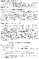
Circuits: Sensitivity: Selectivity: Discriminator Peak to Peak Separation: Frequency Range: Drift: Image Rejection: [F Rejection: Limiter: Antenna Input: Distortion: Frequency Response: Hum Level: Radiation: Output Level: Circuits: Sensitivity: Selectivity: Frequency Range: Image Rejection: IF Rejection: Antenna Input: Distortion: Frequency Response: Hum Level: SPECIFICATIONS FM Armstrong circuit with zero time constant Gated Beam Limiter, Foster-Seeley Discriminator, Automatic Frequency Control and Bar Type Tuning indicator. The RF section consists of a Shaded Grid Low Noise, High Gain VHF Tetrode, High Gain Pentode Mixer followed by three Wide Band IF stages, Limiter, Wide Band (0.6 MC) Discriminator and Cathode Follower Output. 0.95 microvolts. ( 20 db quieting). 1.9 microvolts. ( 30 db quieting ). 240 KC Bandwidth: 6 db down. 0.6 megacycles. 88-108 M.C. ± 20 KC AFC off; +2% KC AFC on. 40 db 70 db Gated beam, constant output. 300 ohms Less than 0.1% IM at 30% modulation. Less than 0.5% IM at 100% modulation. db 20-20,000 c.p.s. including standard 75 microsecond de-emphasis. 60 db below 100% modulation. Within FCC requirements. 1.5 volts for 100% modulation. 5 volts for 30% modulation. AM Low noise, High Gain RF Pentode followed by a Pentagrid converter, two broad band IF stages, infinite impedance detector and 10 KC whistle filter. Separate AVC circuit avoids overloading of detector improving linearity. Exclusive noise filter for noise-free long distance reception. 20 microvolts per meter. Terminal sensitivity 4 microvolts. 16 KC Bandwidth: 6 db down. 530-1640 KC 55 db 55 db Built in Ferrite Loopstick with low impedance Terminal for external antenna. Less than 0.8% harmonic. ± 3 db 20-8,000 cycles. 55 db below 88% modulation.
-
 1
1 -
2
-
3
-
4
-
 5
5 -
 6
6 -
 7
7 -
 8
8 -
 9
9 -
 10
10 -
 11
11 -
 12
12
 |
 |
