Harman Kardon TD3 Owners Manual - Page 3
Installation, Procedure
 |
View all Harman Kardon TD3 manuals
Add to My Manuals
Save this manual to your list of manuals |
Page 3 highlights
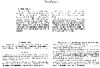
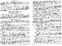
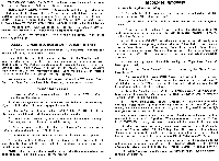
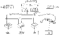
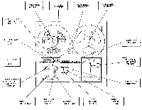
SERVICE POLICY HARMAN-KARDON has established a special consumer division to answer all questions pertinent to the installation and operation of your unit. Please feel free to write us at -any time and we will endeavor to offer prompt and complete advice. If your problem cannot be resolved through our combined efforts, we may wish to refer you to one of our authorized warranty stations. The unit must be shipped via Railway Express, prepaid, to the station designated, accompanied by a brief note describing the exact nature of the difficulty. Under no circumstances should the set be shipped directly to the factory without prior authorization. INSTALLATION PROCEDURE POWER REQUIREMENTS The AC power plug is polarized (that is, it can only be inserted in one direction). Observing the position of the locating key, insert the female end of the power cord supplied into the AC receptacle located on the bottom left-hand side of the tape recorder chassis. Place the other end of the cord into any outlet furnishing 117 volts, 60-cycle AC current. The voltage may vary between 105 and 125 volts. OPERATION PROCEDURE Every control on this stereo tape recorder serves a specific function and is important to the operation of your stereo music system. PLEASE READ the following section carefully to assure full advantage of the performance capa- bilities of your tape recorder. SUPPLY REEL SPINDLE: To record or play back, place the full reel of recording tape on this spindle. Additional information on the feed reel spindle is contained in paragraph "Threading the Tape". TAKE-UP REEL SPINDLE: See Paragraph "Threading the Tape". TAPE SPEED SELECTOR: This is the lever you will use to select the speed you require for playback or recording, namely, 71/2 , 3 3/4 or 1% IPS (inches per second). For quality music recording, it is recommended that 7 1/2 IPS speed be used. For voice recording, a slower speed may be selected, such as 3 3/4 or 1 7/8 IPS. NOTE: Before changing from one tape speed to another, be sure that the power for the recorder is "ON" and the tape "function switch" is in the STOP position to eliminate excessive wear to the drive mechanism. TAPE COUNTER: The three-digit tape counter is connected to the supply hub. It indicates the amount of tape expended when recording or playing back. This counter is provided as a guide when winding or re-winding to a predetermined point on the tape. Push the "Tape Counter Reset" button to return the counter back to its zero or start position. RECORD LEVEL METERS: These meters are used to visually monitor the recording level of the program material and MUST be used in conjunction with the LEFT and RIGHT "record level controls" to maintain a proper level when making recordings. Further information on the use of level meters is contained in paragraph on "Record Procedure". MICROPHONE INPUT JACKS: There are two (2) microphone input jacks to permit making either stereophonic or monophonic recordings. To record stereophonically, use both the LEFT and RIGHT "microphone input jacks". To record monophonically, place one microphone in EITHER the LEFT or the RIGHT microphone input jacks. Additional data on recording may be found under paragraph entitled "Record Procedure." RECORD LEVEL CONTROLS: The Left and Right "record level" controls are used to adjust the incoming program information to the proper recording level which is indicated by the appropriate Left and Right VU meters. To increase the recording levels, rotate these controls in a CLOCKWISE direction. For added convenience, a power ON-OFF switch has been incorporated as an integral part of the Left channel "Record Level Control". To turn the power on, merely rotate the control in a clockwise direction until a "click" is heard. Simultaneously, the TAPE ON indicator light will go on. To turn the power off, rotate the control in a full counterclockwise direction. NOTE: When the tape recorder is not in use, it is recommended that the "function selector" on the recorder be placed in the "STOP" position. MONITOR VOLUME CONTROLS: (TD-3 ONLY) Located directly under each record level control is a larger knob. Rotate this knob in a counterclockwise direction to monitor the source program material. If you wish to monitor the recorded information the instant after it has been recorded, rotate this control in a CLOCKWISE direction. RECORD PUSH BUTTONS: The two (2) orange-colored push buttons located on the lower left portion of the head cover are used to activate the record mechanism and MUST be used simultaneously with the "function selector" switch to start the tape in motion for recording. FUNCTION SELECTOR: The function selector, located on the bottom right- hand corner of your recorder is used to select all forward and reverse motion (Fast Forward, Pause, Run, Stop, and Rewind) of the tape. FAST FORWARD - This position to advance the tape forward. The forward motion can be stopped by turning the Function Selector to the "PAUSE" or "STOP" position. PAUSE - This position stops the advance of the tape in either the RECORD or PLAYBACK mode WITHOUT resetting any of the other functions. To resume operation, merely rotate the "function selector" to the RUN position. RUN - Use this position to advance the tape at a normal rate of speed for playback or recording. When recording, it is necessary to employ this position in conjunction with the "Record Push Buttons", described above. STOP - This position is used to stop the tape. REWIND - This position is used to rewind the tape. To stop at any given point or after the tape is completely rewound, move the "function selector" to STOP. NOTE: When changing from Rewind (REW) to RUN (or vice versa), it is required that you bring the tape to a COMPLETE STOP. When changing from the Fast Forward (F. FWD) to the RUN positions, you must bring the tape to a complete stop in the PAUSE position. ALWAYS keep the selector in the STOP position when the recorder is not in use. 1
-
 1
1 -
 2
2 -
 3
3 -
 4
4 -
 5
5 -
 6
6 -
 7
7 -
 8
8 -
 9
9 -
10
 |
 |
