Hayward 1.5in x 2in Suction Outlet Assembly-White 8 inch Dual Suction Outlet M - Page 4
Installation Instructions
 |
View all Hayward 1.5in x 2in Suction Outlet Assembly-White manuals
Add to My Manuals
Save this manual to your list of manuals |
Page 4 highlights
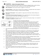
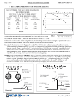
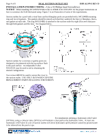
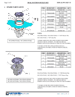
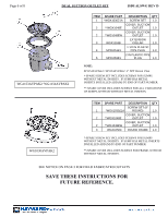
Page 4 of 8 DUAL SUCTION OUTLET SET ISDUALSWG REV D INSTALLATION INSTRUCTIONS: - Use a #2 Philips head Screwdriver. NOTICE: When installing WG1030AVPAK2 refer to ASME A112.19.8-2007 for the proper instructions on how to construct the field-fabricated sump. Figure 2 is an illustration of some of the requirements. Suction outlets for a pool with a vinyl liner and for fiberglass pools are provided with a WG1048B mounting ring and two (2) gaskets. The gaskets should be placed such that they sandwich the liner or fiberglass, that is, one gasket on each side. The ring (WG1048B) is attached to the suction outlet by eight (8) screws that pass through both gaskets and the liner. See diagram below. Suction outlets for a concrete or gunite pools are designed to be plastered with the top surface flush to the pool surface. An Adjustable Collar WG1051X may be used to aid in obtaining the desired configuration. Two screws MUST be used to secure the cover to the suction outlet. USE ONLY HAYWARD GENUINE REPLACEMENT PARTS INCLUDING THE SCREWS. For installations utilizing a hydrostatic relief valve (SP1056), using a collector tube (SP1055) will maintain a clear path to the hydrostatic valve. At least one hydrostatic relief valve in a set of suction outlets will allow hydrostatic uplift pressure caused by ground water to be relieved into the pool or spa.
-
 1
1 -
 2
2 -
 3
3 -
 4
4 -
 5
5 -
 6
6 -
 7
7 -
 8
8
 |
 |
