Hayward AQL2-WW-PS-4 Aqua-Logic-Pro-Logic-Remote-Display-Owners-Manual-092147C - Page 2
Installation
 |
View all Hayward AQL2-WW-PS-4 manuals
Add to My Manuals
Save this manual to your list of manuals |
Page 2 highlights
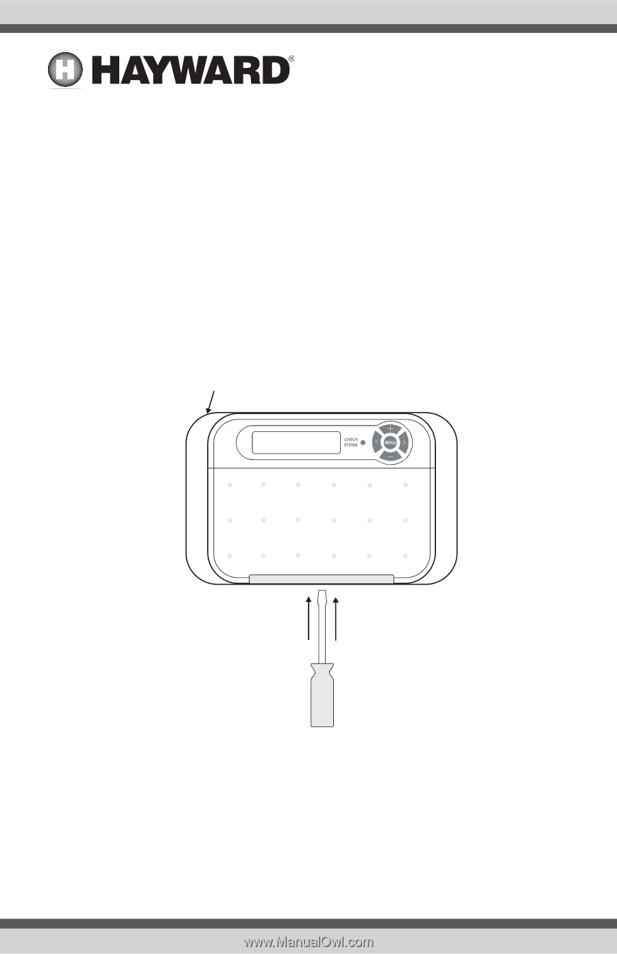
COMPATIBILITY: This remote display is compatible with all Pro Logic PS-4/8/16 models and for all Aqua Logic PS-4/8/16 systems running main software r2.00 or higher. Installation Mounting The AQL2-Wx-PS-x Remote Display must be mounted indoors or in a weather protected area (rain should never hit the remote display). Up to 3 remote displays can be installed. The remote display is designed to mount onto a standard electrical utility box (same size as used for a triple light switch) or can be mounted directly onto any wall surface. When selecting a location, note that the wire to the Pro Logic/Aqua Logic main unit must be no more than 500 ft (160m) long. Follow the steps below: 1. Remove the remote display baseplate from the cover by inserting a screwdriver in the slot shown below. Lift up on the cover while pushing gently with the screwdriver. Bezel (use is optional) Push Screwdriver blade through slot and pull up cover 2. If bezel will be used, snap baseplate into bezel before mounting. 3. Screw the baseplate in the desired position (screws supplied by installer). 2 USE ONLY HAYWARD GENUINE REPLACEMENT PARTS
-
 1
1 -
 2
2 -
 3
3 -
 4
4 -
 5
5 -
 6
6 -
 7
7 -
 8
8
 |
 |