Hayward Aqua Plus® Model: PL-PLUS Installation - Page 13
Electrical Wiring - aqua plus control panel
 |
View all Hayward Aqua Plus® manuals
Add to My Manuals
Save this manual to your list of manuals |
Page 13 highlights
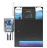
4. Electrical Wiring Remote Keypad Temp Sensor Inputs External Input Heater Output Valve Connectors Wireless Base Receiver Connector x x AQL-CHEM Connector "Local" Display Flow Switch Cell Connector Subpanel High Voltage Relays Control Power Input pH Dispense Output Ground Bus Bar Bonding Lug(s) The Aqua Plus Control Center requires both high and low voltage connections. Low voltage connections will be made to actuators, sensors, remote keypad, etc. High voltage connections will be made to pumps, lights, etc., as well as providing direct input power to the Control Center. Always: -Ensure that Power is disconnected prior to doing any wiring -Follow all local and NEC (CEC if applicable) codes -Use copper conductors only Main Service (Power to the Circuit Breaker Subpanel) The Aqua Plus circuit breaker subpanel is rated for 100A service. Run properly rated conductors (L1, L2, N, and ground) from the primary house electrical panel to the main power connections on the Aqua Plus circuit breaker base. The connection at the main house panel should be to a 240VAC circuit breaker rated at 100A maximum. Grounding and Bonding Connect a ground wire from the primary electrical panel to the Aqua Plus ground bus bar. Also ground each piece of high voltage (120 or 240VAC) equipment that is connected to the Aqua Plus control relays or circuit breakers. The Aqua Plus should also be connected to the pool bonding system by an 8AWG (6AWG for Canada) wire. A lug for bonding (2 for Canada) is provided on the outside/bottom of the Aqua Plus enclosure. Circuit Breaker Installation and Wiring Circuit breakers are to be supplied by the installer. Refer to the circuit breaker chart below for a list of suitable circuit breakers that can be used. Follow the code and the circuit breaker manufacturer's rating requirements regarding the size and temperature rating for wiring. Note that some pool equipment may be required to be connected to ground fault circuit breakers-check local and NEC (CEC) codes. Manufacturer SUITABLE LISTED BREAKERS Single Double Twin Quad GFCB Tightening Filler Plates Torque Cutler-Hammer BR Murray MP-T Siemens QP Square D HOM Thomas & Betts TB G.E. THQL BR MP-T QP HOM TB THQL BRD MH-T QT HOMT TBBD BRD MH-T QT HOMT TBBQ GFCB MP-GT QPF HOM-GFI GFB THQL-GF BRFP LX100FP QF3 HOMFP FP-1C-TB TFH 25lb-in 25lb-in 25lb-in 25lb-in 25lb-in 25lb-in 10
-
 1
1 -
2
-
3
-
4
-
5
-
6
-
7
-
 8
8 -
 9
9 -
 10
10 -
 11
11 -
 12
12 -
 13
13 -
 14
14 -
 15
15 -
 16
16 -
 17
17 -
 18
18 -
19
-
20
-
21
-
22
-
23
-
24
-
25
-
26
-
27
-
28
-
29
-
30
-
31
-
32
-
33
-
34
-
35
-
36
 |
 |
