Hayward Aqua Rite Salt Chlorination AQ-RT-PRO prior to Oct 08 - Page 17
Plumbing
 |
View all Hayward Aqua Rite Salt Chlorination manuals
Add to My Manuals
Save this manual to your list of manuals |
Page 17 highlights
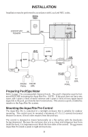
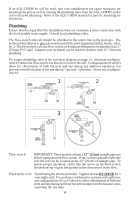
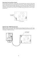
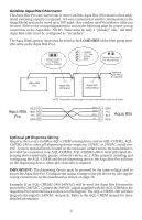
If an AQL-CHEM kit will be used, take into consideration the space necessary for mounting the unit as well as running the plumbing lines from the AQL-CHEM's probe cell to the pool plumbing. Refer to the AQL-CHEM manual for specific mounting instructions. Plumbing Ensure that the Aqua Rite Pro installation does not constitute a cross connection with the local potable water supply. Consult local plumbing codes. The flow switch and cell should be plumbed in the return line to the pool/spa. The preferred installation is after (downstream) all the pool equipment (filter, heater, solar, etc.). The electrolytic cell and flow switch tee fitting are designed to be plumbed into 2" (51mm) PVC pipe. Adapters (not included) can be used for systems with 1½" (38 mm) plumbing. For proper plumbing, refer to the overview diagram on page 13. Alternate configurations #1 shows the flow switch can also be in front of the cell. Configurations #2 and #3 allow for chlorination of both the pool and spa during spa spillover operation, but prevent overchlorination of the spa during "spa only" operation. Never use configuration #4. 1 2 12" min 12" min 3 4 Flow Switch: IMPORTANT: There must be at least a 12" (25cm) straight pipe run before (upstream) the flow switch. If the switch is plumbed after the cell, the cell can by counted as the 12" (25cm) of straight pipe. To ensure proper operation, verify that the arrow on the flow switch (located on top of gray hex) points in the direction of water flow. Electrolytic Cell: Install using the unions provided. Tighten unions BY HAND for a watertight seal. For pool/spa combination systems with spillover, use configurations #2 or #3 above to allow chlorination of both the pool and spa during spillover but preventing overchlorination when operating the spa only. 14
-
 1
1 -
2
-
3
-
4
-
5
-
6
-
7
-
8
-
9
-
10
-
11
-
 12
12 -
 13
13 -
 14
14 -
 15
15 -
 16
16 -
 17
17 -
 18
18 -
 19
19 -
 20
20 -
 21
21 -
 22
22 -
23
-
24
 |
 |
