Hayward CSPAXI11 Spa Heaters - Page 4
Volts, Acaution, Awarning
 |
View all Hayward CSPAXI11 manuals
Add to My Manuals
Save this manual to your list of manuals |
Page 4 highlights
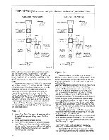
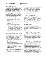
C-SPA-XI W Wiring:Observe correct wiring size betweenjob site breaker andjunction box inheater. 240-VOLTS 5.5KW JUNCTION BOX Li L2 1-4 T SURFACE MOUNT HI-LIMIT THERMOSTAT 6 co ' CONTACTOR 240 V COIL • 4 /7 t7 GROUND #18 BLUE 3 a g •. HEATING ELEMENT „ < PRESSURE SWITCH N.O. IMMERSION THERMOSTAT ADJUSTABLE 240-VOLTS 11KW JUNCTION BOX Ll L2 . p /7 L7 GROUND SURFACE MOUNT HI-LIMIT THERMOSTAT :C CONTACTOR 240 V COIL • 6 i HEATING ELEMENT HEATING ELEMENT 8 BLUE o • ,c°,' g_, * V Le, •
-
 1
1 -
 2
2 -
 3
3 -
 4
4 -
 5
5 -
 6
6 -
 7
7 -
 8
8
 |
 |

C
-SPA
-XI
W
Wiring:
Observe
correct
wiring
size
between
job
site
breaker
and
junction
box
in
heater.
240
-VOLTS
5.5KW
240
-VOLTS
11KW
4
JUNCTION
BOX
Ll
L2
/7
L
7
JUNCTION
BOX
Li
L2
/7
t
7
.
p
GROUND
1
-
4
GROUND
T
SURFACE
MOUNT
HI
-LIMIT
THERMOSTAT
SURFACE
MOUNT
HI
-LIMIT
THERMOSTAT
:C
8
BLUE
6
#18
BLUE
'
co
3
CONTACTOR
240
V
COIL
•
•
o
,c'
°,
*
g_
,
V
CONTACTOR
240
V
COIL
•
•
a
.
g
6
i
L
e,
'
•
<)
.
PRESSURE
SWITCH
N.O.
„
<
PRESSURE
SWITCH
N.O.
HEATING
HEATING
ELEMENT
ELEMENT
IMMERSION
THERMOSTAT
ADJUSTABLE
HEATING
•
•
IMMERSION
THERMOSTAT
ADJUSTABLE
PILOT
LAMP
u
Figure
4
ELEMENT
PILOT
LAMP
Figure
5
latest
edition)
and
in
accordance
with
local
codes
and/or
electric
utility
requirements.
It
is
recom-
mended
that
the
heater
supply
circuit
be
protected
by
a
ground
-fault
circuit
-interrupter
(GFCI)
in
accor-
dance
with
Article
680-5(b)
of
the
National
Electrical
Code.
A
wire
connector
marked,
"GROUND"
is
provided
within
the
control
box.
To
reduce
the
risk
of
electri-
cal
shock,
connect
this
terminal
or
connector
to
the
grounding
terminal
of
the
electrical
service
or
supply
panel
with
a
continuous
green
insulated
copper
wire
equivalent
in
size
as
specified
for
Ground
Wire
Size
on
Figure
2.
Grounding
must
be
in
accordance
with
Article
250
of
the
National
Electri-
cal
Code.
A
bonding
wire
must
be
connected
to
the
bonding
lug
on
the
heater
exterior
right
side
Refer
to
Article
250
Part
G.
for
bonding
requirements
of
the
National
Electrical
Code.
Be
sure
all
connections
are
clean
and
secure.
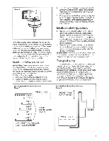
Startup:
1.
Clean
filter.
Start
filter
pump.
Make
sure
all
air
is
out
of
the
spa
plumbing
lines.
Wait
five
minutes.
2.
Close
electrical
disconnect
switch.
3.
Set
C
-SPA
-XI
thermostat
at
desired
tempera-
ture.
Disconnect
time
clock
during
initial
heat
-
up.
Your
outlet
temperature
will
feel
just
slightly
warmer
than
the
inlet
temperature.
Do
not
be
concerned;
this
is
normal.
Operation:
The
adjustable
external
thermostat
on
your
C
-SPA
-XI
heater
has
a
"positive
off"
provision
at
the
lowest
temperature
setting.
Movement
of
the
ther-
mostat
knob
to
this
position
will
prevent
operation
of
the
heater.
ACAUTION:
Internal
components
of
the
heater
are
still
"live"
electrically
even
with
the
thermostat
turned
off.
The
main
breaker
or
disconnect
for
this
unit
must
be
turned
off
before
servicing
the
unit.
The
spa
temperature
may
be
adjusted
by
turning
the
thermostat
knob
up
or
down
until
the
spa
temperature
reaches
the
desired
level.
Adjustments
should
be
made
in
small
increments
and
sufficient
time
should
be
allowed
for
the
body
of
water
to
heat
or
cool
before
further
adjustments
are
made.
When
the
exact
desired
comfort
level
is
reached,
you
may
wish
to
lock
the
thermostat
dial
lock
at
this
position
by
tightening
the
dial
lock
screw.
The
pilot
lamp
on
your
C
-SPA
-XI
is
an
indicator
that
the
element(s)
should
be
operating.
It
will
cycle
on
and
off
with
the
thermostat.
AWARNING:
Spa
temperature
is
to
be
determined
by
an
accurate
spa
thermometer.
"Test"
the
water
temperature
with
your
hand
before
entering
the
spa.
See
"Warning"
on
page
2.
Factory
installed
pressure
switch:
The
function
of
the
pressure
switch
is
to
shut
the
spa
heater
off
if
the
pump
is
turned
off
or
if
the
4