Hayward E-Command 4 Model: ALL MODELS Installation - Page 15
VSC Pump Address Setting, Temperature Sensors
 |
View all Hayward E-Command 4 manuals
Add to My Manuals
Save this manual to your list of manuals |
Page 15 highlights
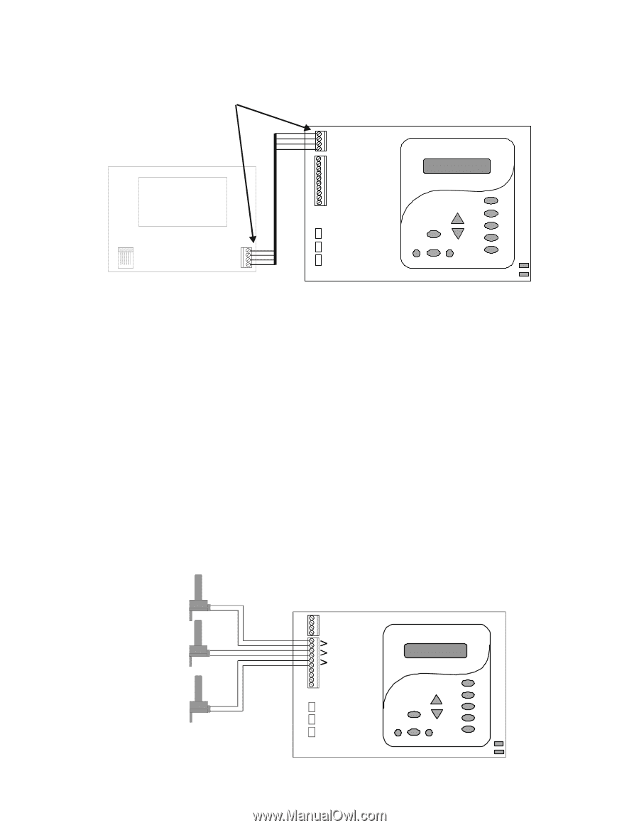
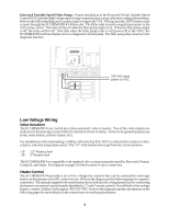
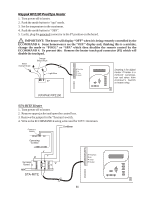
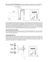
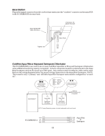
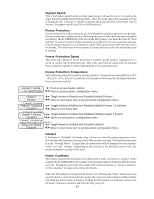
Hayward Variable Speed Filter Pump: Refer to the diagram below for proper low voltage communication wiring between the ECOMMAND 4 and the Hayward Tristar Variable Speed Control (VSC). Connect screw terminals "1" to "1", "2" to "2", etc. RED BLK YEL GRN VSC 4 GRN 3 2 1 YEL BLK RED Use four conductor cable (typically phone cable) for communications connection between the VSC and the ECOMMAND 4. The maximum wiring distance is 500 feet (160 meters). Note that the terminals on both the VSC interface board and the ECOMMAND 4 main board are numbered. The terminal connections should be matched between both terminal blocks (connect 1 to 1, 2 to 2, etc.). The communications cable should be routed through the knockout hole on the left side of the VSC enclosure, and a watertight fitting should be used to keep water and debris out of the opening. The communications cable should also be routed away from the ECOMMAND 4 and VSC power connections if possible. VSC Pump Address Setting The VSC address must be set to 001 when using the VSC with the ECOMMAND 4. Refer to the TriStar Pump Owner's Manual (IS3220VSC) and Hayward document IS3220VSCAQLL for specific instructions on setting the pump address. Temperature Sensors The ECOMMAND 4 utilizes 10K ohm thermistor type sensors. Three sensors (water temperature, air temperature and solar temperature) are included. If the ECOMMAND 4 is being used to control a solar heating system, the solar sensor is required. The sensors are provided with a 15 ft. cable. If a longer cable is required, contact the Goldline service dept. for information on suitable cable types and splices. See page 6 and the diagram below for installation information. POOL/SPA SENSOR AIR SENSOR SOLAR/SPA SENSOR Pool/Spa Air Solar 12
-
 1
1 -
2
-
3
-
4
-
5
-
6
-
7
-
8
-
9
-
 10
10 -
 11
11 -
 12
12 -
 13
13 -
 14
14 -
 15
15 -
 16
16 -
 17
17 -
 18
18 -
 19
19 -
 20
20 -
21
-
22
-
23
-
24
-
25
-
26
-
27
-
28
-
29
-
30
-
31
-
32
 |
 |