Hayward Easy-Clear™ C5501575 Series Easy Clear - Page 2
Parts, Models C-400-1540lsh, C-400-1575 And C-550-1575, Series, Systems
 |
View all Hayward Easy-Clear™ manuals
Add to My Manuals
Save this manual to your list of manuals |
Page 2 highlights
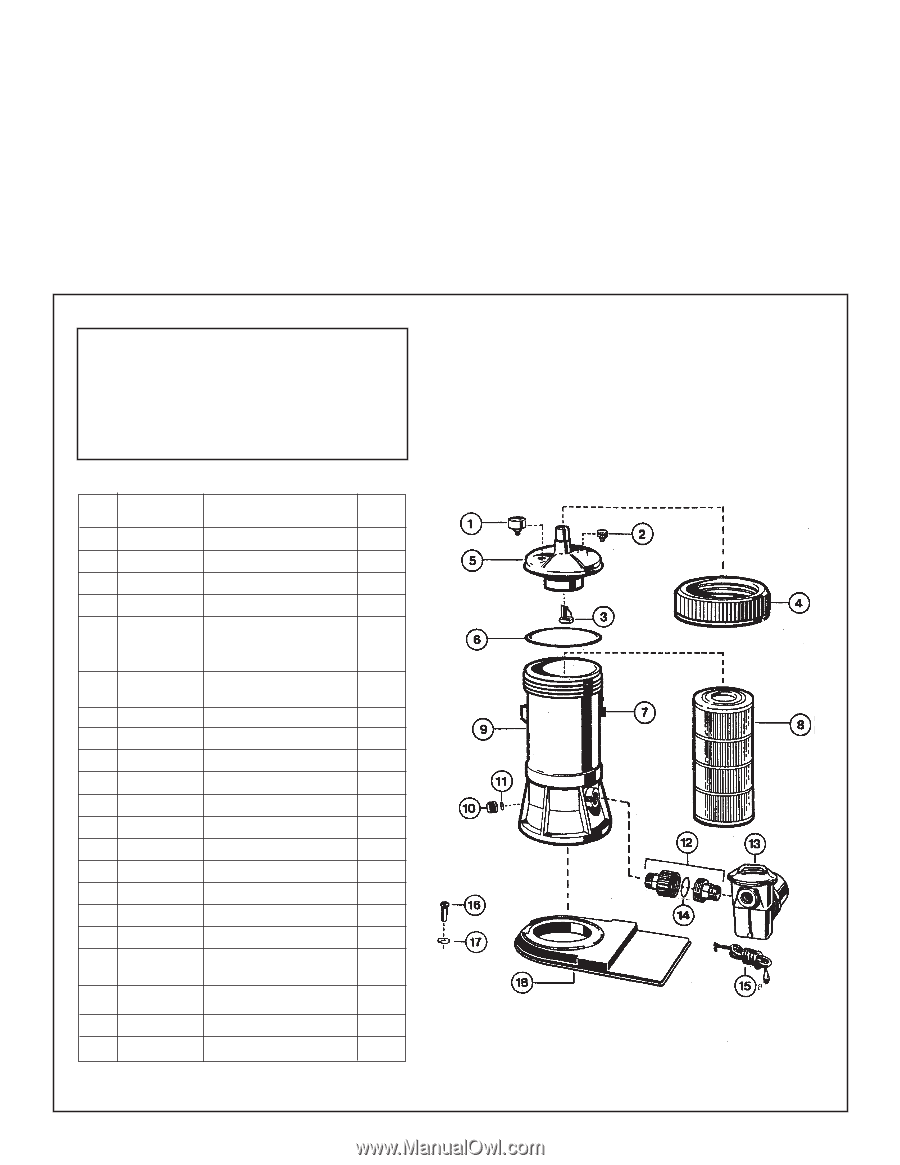
4. Tighten pump base mounting bolts, if loose. 5. Securely hand tighten the union nut between the filter and pump. 6. Connect the pool suction plumbing between the skimmer, pool outlet and the pump. 7. Connect the pool return (inlet) plumbing. 8. If pressure gauge is not installed, apply Teflon tape to the gauge threads, and carefully screw the gauge into the threaded hole in the filter cover. 9. A drain plug is furnished with each filter and is all that is needed for complete filter draining. A manual air vent valve is furnished to aid in bleeding off unwanted air when starting the filter. 10. All electrical connections should be made in accordance with local codes. 11. Check for joint leaks before operating the system. 12. Refer to pump instruction booklet for pump information. PARTS Models C-400-1540LSH, C-400-1575 and C-550-1575 SERIES SYSTEMS REF. NO. 1 2 3 4 PART NO. EXC2710 ECX1322-A ECX4077-B-1 CX400-C DESCRIPTION Gauge Vent Valve w/O-Ring Check Valve Locking Ring NO. REQ'D. 1 1 1 1 Filter Head (Cover), 5 CX400-BA w/Check Valve and 1 Locking Ring 6 CX400-G Filter Head (Cover) O-Ring 1 7 CX400-D Locking Ring Latch 1 a 8a CX410-RE Filter Element (40 Sq. Ft.) 1 b 8b CX550-RE Filter Element (55 Sq. Ft.) 1 9a CX400-AA Filter Body (C-400) 1 9b CX550-AA Filter Body (C-500) 1 10 SX200-Z-8 Drain Cap 1 11 SX200-Z-9 Gasket 1 12 SP-1480 1-1/2" Male Union 1 13 SP-1575-1 Power-Flo LX Pump 1 14 SPX1425-Z-6 O-Ring 1 15a SPX1500-WA 6 Ft. Cord Set 1 15b SPX1550-WA1 3 Ft. Twist Lock Cord Set (Not Shown) 1 16 ECX1108 Pump Mounting Screw 2 17 ECX1109 Washer 2 18 ECX1161 Platform Base 1 a b a
-
 1
1 -
 2
2 -
 3
3 -
 4
4
 |
 |