Hayward HeatPro Heat Pump Heat Pro All Models - Page 33
dual mechanical units, Intermatic, AquaSwitch, Connection to AquaLink, Compool, and Hayward, Remote
 |
View all Hayward HeatPro Heat Pump manuals
Add to My Manuals
Save this manual to your list of manuals |
Page 33 highlights
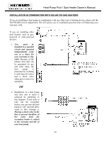
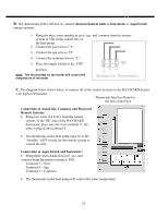
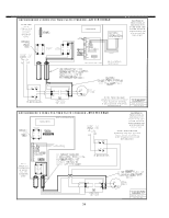
B. The instructions below tell how to connect dual mechanical units to Intermatic or AquaSwitch remote systems: 1. Bring the three wires marked as pool, spa, and common from the remote system to TB2 in the control box of the heat pump. 2. Connect the pool wire to "L' 3. Connect the spa wire to "H" 4. Connect the common wire to "C" 5. Place the toggle switch in the "OFF" position Note: The thermostats on the heater still control the temperature of the water. C. The diagram below shows where to connect all of the remote systems to the HAYWARD heaters with digital thermostats. Thermostat Interface Board in the unit control box Connection to AquaLink, Compool, and Hayward Remote Systems: • Bring two wires (24 VAC) from the remote system. In the TB1 area of the HAYWARD thermostat, place one wire into terminal 11, the other is placed into terminal 4. • The thermostat on the heat pump must be in the "Standby" (OFF) mode for the remote system to control the unit. Connection to Aqua Switch and Intermatic: • Bring three wires marked as pool, spa, and common from the remote system to TB1: Terminal 7 = Pool Terminal 9 = Spa Terminal 2 = Common • The thermostat on the heat pump will control the water temperature. 32
-
 1
1 -
2
-
3
-
4
-
5
-
6
-
7
-
8
-
9
-
10
-
11
-
12
-
13
-
14
-
15
-
16
-
17
-
18
-
19
-
20
-
21
-
22
-
23
-
24
-
25
-
26
-
27
-
 28
28 -
 29
29 -
 30
30 -
 31
31 -
 32
32 -
 33
33 -
 34
34 -
 35
35 -
 36
36 -
 37
37 -
 38
38 -
39
-
40
-
41
-
42
-
43
 |
 |
