Hayward Low Velocity Low Velocity Suction Outlet Manual - Page 5
Dual Suction Outlet Set, Installation Instructions, Parts Lists
 |
View all Hayward Low Velocity manuals
Add to My Manuals
Save this manual to your list of manuals |
Page 5 highlights
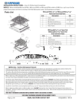
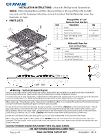
INSTALLATION INSTRUCTIONS: - Use a #2 Philips head Screwdriver. NOTICE: When installing WG1031LVPAK2, WG1032LVPAK2 or WG1033LVPAK2 refer to ASME A112.19.8-2007 for the proper instructions on how to construct the field-fabricated sump. See Illustration on Page 7 • PARTS LISTS WG1033LVPAK2 18" x 18" Frame and Cover Dual Pack Item Description Qty 1 Cover 8 2 Inner Frame 3 Machine Screw #10-24 4 #13-9 Self Taping Screw 5 Outer Frame 8 (Installed) 32 32 (Installed) 2 WGX1033BLV Spare Part Cover and Inner Frame Item Description Qty 1 Cover 4 2 Inner Frame 4 3 Machine Screw #10-24 16 4 #13-9 Self Taping Screw 16 3 4 Warning - Suction Entrapment Hazard. Suction in suction outlets and/or suction outlet covers which are installed in a small area and/or below the surrounding surface can cause severe injury or death due to body entrapment hazard. ·To reduce the risk of body entrapment, installation of the field fabricated sumps must be such that the top of the mounted cover is a minimum of 1 1/2" above the finished pool surface over an area larger than 40" on a diagonal. When replacing a SP1031B grate with a replacement cover WGX1033BLV, in an existing SP1033A Outer Frame (One that does not have inner frame installed), the grate is removed and discarded. Locate the Inner Frame (Item 2) and using four (4) screw #13-9 x 5/8" (Item 4) Secure Inner Frame to Outer Frame. Should you not be able to secure the Inner Frame to the Outer Frame using the existing holes in the Outer Frame; drill four.149" (#25) diameter holes in the Outer Frame, using the holes in the Inner Frame to locate the holes to drill in the Outer Frame. Using four (4) screw #13-9 x 5/8" (Item 4) Secure Inner Frame to Outer Frame utilizing the four (4) new holes. Locate the Cover (Item 1) and using four (4) #10-24 x 15/16" long screws (Item 3) Secure to the Inner Frame. When replacing a WG1033B or a WG1033BLV cover, Do NOT remove the Inner Frame from the Square Frame unless it is damaged. The four screws in the corners of the cover are retained in the cover. New screws should be used whenever the cover is replaced. USE ONLY HAYWARD GENUINE REPLACEMENT PARTS INCLUDING SCREWS. USE ONLY HAYWARD GENUINE REPLACEMENT PARTS Page 5 of 8 DUAL SUCTION OUTLET SET ISSQUARELV REV B
-
 1
1 -
 2
2 -
 3
3 -
 4
4 -
 5
5 -
 6
6 -
 7
7 -
 8
8
 |
 |
