Hayward S220T Models: S220T S244T - Page 3
Model S180t, S210t, S220t, S244t, Warning - sand filter parts
 |
View all Hayward S220T manuals
Add to My Manuals
Save this manual to your list of manuals |
Page 3 highlights
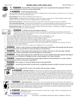
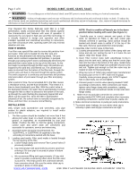
Page 3 of 8 MODEL S180T, S210T, S220T, S244T IS210T-06 Rev A WARNING - To avoid dangerous or fatal electrical shock, turn OFF power to motor before working on electrical connections. WARNING - Failure to bond pump to pool structure will increase risk for electrocution and could result in injury or death. To reduce the risk of electric shock, see installation instructions and consult a professional electrician on how to bond pump. Also, contact a licensed electrician for information on local electrical codes for bonding requirements. Your Hayward Pro Series high-rate sand filter is a high performance, totally corrosion-proof filter that blends superior flow characteristics and features with ease of operation. It represents the very latest in high-rate sand filter technology. It is virtually foolproof in design and operation and when installed, operated and maintained according to instructions, your filter will produce clear, sparkling water with only minimal attention and care. HOW IT WORKS Your filter uses special filter sand to remove dirt particles from pool water. Filter sand is loaded into the filter tank and functions as the permanent dirt removing media. The pool water, which contains suspended dirt particles, is pumped through your piping system and is automatically directed by the patented filter control valve to the top of the filter tank. As the pool water is pumped through the filter sand, dirt particles are trapped by the sand bed, and filtered out. The cleaned pool water is returned from the bottom of the filter tank, through the control valve and back to the pool through the piping system. This entire sequence is continuous and automatic and provides total recirculation of pool water through your filter and piping system. NOTE: Check to confirm all laterals are in the down position before loading with sand. (See Figure A.) d. Carefully pour in correct amount and grade of filter sand, as specified on Table 1. (Be sure center pipe remains centered in opening). Sand surface should be leveled and should come to within 6" of the top of the filter tank. Remove sand shield from internal pipe. 4. Assemble Filter Control Valve to filter tank. a. Loosely pre-assemble both halves of the clamp with one screw and one nut, turning the nut 2 or 3 turns. Do not tighten. Wipe filter flange clean. b. Insert Filter Control Valve (with valve/flange 0-ring in place) into the tank neck, taking care that the center pipe slips into the hole in the bottom of the valve. Install clamp around tank and valve flange and assemble second screw and nut. Tighten just enough so that the valve may be rotated on tank for final positioning. c. Wrap two turns of Teflon pipe sealant tape manufactured for plastic pipe on the ¼" NPT male end of gauge. Carefully screw pressure gauge, into 1/4"NPT tapped hole in valve body. Do not over tighten. After a period of time, the accumulated dirt in the filter causes a resistance to flow, and the flow diminishes. This means it is time to clean (backwash) your filter. With the control valve in the backwash position, the water flow is automatically reversed through the filter so that it is directed to the bottom of the tank, up through the sand, flushing the previously trapped dirt and debris out the waste line. Once the filter is backwashed (cleaned) of dirt, the control valve is manually resequenced to Rinse, and then Filter, to resume normal filtering. d. Connect pump to control valve opening marked PUMP according to instructions. After connections are made, tighten valve flange clamp with screwdriver, tapping around clamp with screwdriver handle to help seat valve flange clamp. 5. Make return to pool pipe connection to control valve opening marked RETURN and complete other necessary plumbing connections, suction lines to pump, waste, etc. 6. Make electrical connections to pump per pump instructions. INSTALLATION Only simple tools (screwdriver and wrenches), plus pipe sealant for plastic adapters, are required to install and/or service the filter. 7. To prevent water leakage, be sure winter drain cap is securely in place and all pipe connections are tight. 1. The filter system should be installed, not more than 6 feet above pool water level, on a level concrete slab, very firm ground, or equivalent, as recommended by your pool dealer. Position the filter so that the piping connections, control valve and winter drain are convenient and accessible for operation, service and winterizing. 2. Assemble pump and pump mounting base, No. S160TPAK1, or S160TPAK3 (if supplied) to the filter according to instructions packed with the base. 3. Loading sand media. Filter sand media is loaded through the top opening of the filter. a. Loosen flange clamp and remove Filter Control Valve (if previously installed). b. Cap internal pipe with sand shield to prevent sand from entering it. Be sure pipe is securely in place in bottom underdrain hub. c. We recommend filling tank approximately 1/2 way with water to provide a cushioning effect when the filter sand is poured in. This helps protect the underdrain laterals from excessive shock. (Be sure the winter drain cap is securely in place on drain pipe). WWW.HAYWARDPOOL.COM USE ONLY HAYWARD GENUINE REPLACEMENT PARTS
-
 1
1 -
 2
2 -
 3
3 -
 4
4 -
 5
5 -
 6
6 -
 7
7 -
 8
8
 |
 |