Hayward Super Pump All Super Pump models - Page 5
Product Specifications, Installation Instructions, WARNING - sp2607x10
 |
View all Hayward Super Pump manuals
Add to My Manuals
Save this manual to your list of manuals |
Page 5 highlights
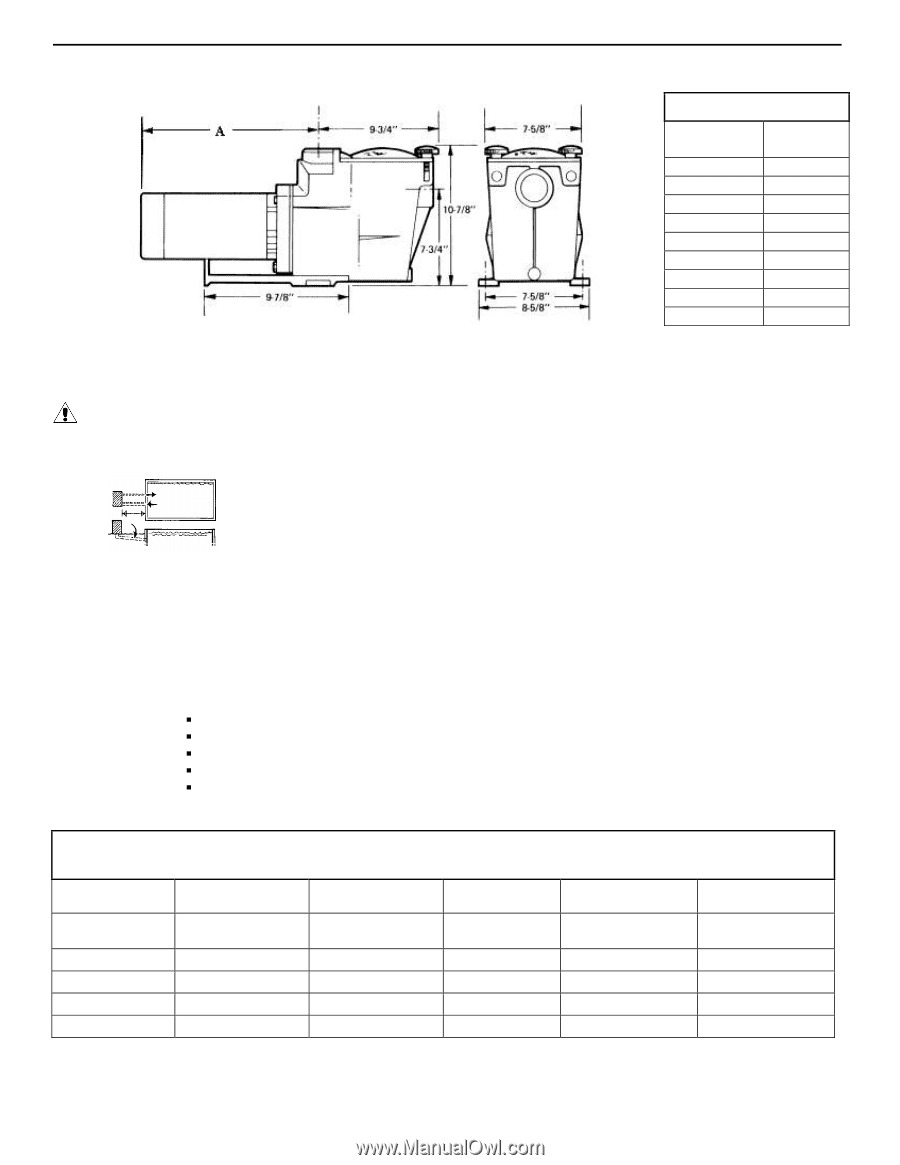
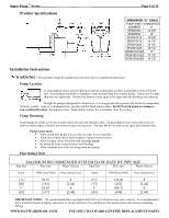
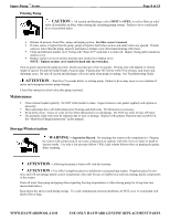
Super Pump ™ Series__________ Product Specifications _____ Page 5 of 15 DIMENSION "A" TABLE PUMP PART DIMENSION NUMBER A SP2600X5 13 3/8" SP2605X7 14" SP2607X10 14 3/8" SP2610X15 15 1/2" SP2615X20 16 1/2" SP2621X25 16 1/2" SP2607X102S 17" SP2610X152S 17 1/2" SP2615X202S 18 1/2" Installation Instructions WARNING - This product should be installed and serviced only by a qualified professional. Pump Location Locate pump as close to pool as practical and run suction lines as direct as possible to reduce friction loss. Suction lines should have continuous slope upward from lowest point in line. Joints must be tight (but not over-tightened). Suction line diameter must equal or be larger than the discharge line diameter. Though the pump is designed for outdoor use, it is strongly advised to protect the electrical components from the weather. Select a well-drained area, one that will not flood when it rains. Do NOT install pump in a damp or non-ventilated location. Keep motor clean. Pump motors require free circulation of air for cooling. Pump Mounting Install pump on a firm, level base or pad to meet all local and national codes. Fasten pump to base or pad with screws or bolts to further reduce vibration and stress on pipe or hose joints. The base MUST be solid, level, rigid, and vibration free. Pump mount must: ƒ Allow pump inlet height to be as close to water level as possible. ƒ Allow use of short, direct suction pipe (to reduce friction losses). ƒ Allow for gate valves in suction and discharge piping. ƒ Be protected from excess moisture and flooding. ƒ Allow adequate access for servicing pump and piping. Pipe Sizing Chart MAXIMUM RECOMMENDED SYSTEM FLOW RATE BY PIPE SIZE Pipe Size Flow rate Water Velocity Pipe Size Flow rate Water Velocity [mm] GPM [Liter/Min] ft/sec [meters/sec] [mm] GPM [Liter/Min] ft/sec [meters/sec] 1 ½" 50.76 8 2 ½" 119.40 8 [50] [192] [2.44] [75] [452] [2.44] 2" 83.65 8 3" 184.32 8 [63] [317] [2.44] [90] [698] [2.44] IMPORTANT NOTES - No system should allow any higher than 8-ft/sec [2.44 meters/sec] water velocity. It is recommended that a minimum length of piping, equivalent to 10 pipe diameters, be used between the pump suction inlet and any plumbing fittings. WWW.HAYWARDPOOL.COM USE ONLY HAYWARD GENUINE REPLACEMENT PARTS
-
 1
1 -
 2
2 -
 3
3 -
 4
4 -
 5
5 -
 6
6 -
 7
7 -
 8
8 -
 9
9 -
 10
10 -
 11
11 -
12
-
13
-
14
-
15
 |
 |