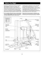
HealthRider 230 English Manual - Page 8
Bolt through the Weight Guide and the Weight Base.
 |
View all HealthRider 230 manuals
Add to My Manuals
Save this manual to your list of manuals |
Page 8 highlights
10. Attach two Bumpers (40) to the Weight Base (5) with two #8 x 1Ó Screws (78). Insert the two Weight Guides (15) through the indicated holes in the Weight Base (5). See the inset drawing. Press two Weight Inserts (77) into the indicated holes in each Weight (21). Make sure the large pin groove is pointed downward, as shown. Slide all of the included Weights (21) onto the two Weight Guides (15). Make sure the Weights are oriented correctly. The adjustment holes must be turned towards the center of the unit, as shown. For packaging purposes, the Top Weight (16) is mounted in the upper threaded hole in the Weight Tube (17). Unless you have bought the Weight Expansion Set with five extra weight plates along with your system, the Top Weight must be moved. Use the Allen Wrench (100) to loosen the Button Head Screw (52) and slide the Top Weight down to the lower of the two threaded holes in the Weight Tube, as shown. Lubricate the insides of the holes in the Top Weight (16). Press the Weight Tube Bumper (18) into the indicated end of the Weight Tube (17). Slide the Weight Tube (17) with the Top Weight (16) onto the Weight Guides (15). Attach the Allen Wrench Holder (79) to the indicated location on the Seat Frame (7) Locate the decal sheet with the stickers showing the numbers 1 through 15. Place a sticker on each Weight (21) and the Top Weight (16) right next to the adjustment holes (see the inset drawing). The Top Weight must have the number 1 on it. 11. Slide a 3/8Ó Flat Washer (55) and a 5/8Ó x 1/2Ó Bushing (85) onto a 3/8Ó x 2 3/4Ó Bolt (47). Line up the hole in the indicated Weight Guide (15) with the hole in the Weight Base (5). Slide the 3/8Ó x 2 3/4Ó Bolt through the Weight Guide and the Weight Base. Slide a 5/8Ó x 1/2Ó Bushing (85) onto the Bolt. Secure the Bolt with a 3/8Ó Flat Washer (55) and a 3/8Ó Nylon Locknut (50). 10 15 Lubricate 16 52 2 78 5 40 11 5 55 50 77 21 Large Pin Number Groove Decal 17 Place Stickers on this side 18 Adjustment Holes on this side 7 100 21 79 15 55 47 85 85 12. Attach the upper ends of the Weight Guides (15) to 12 the welded bracket underneath the Weight Upright (2) with two 3/8Ó x 1 3/4Ó Bolts (57) and two 3/8Ó Nylon Locknuts (50). Tighten, but do not overtighten, the 2 Nylon Locknuts. 50 Welded Bracket 57 15 8
-
 1
1 -
2
-
 3
3 -
 4
4 -
 5
5 -
 6
6 -
 7
7 -
 8
8 -
 9
9 -
 10
10 -
 11
11 -
 12
12 -
 13
13 -
14
-
15
-
16
-
17
-
18
-
19
-
20
-
21
-
22
-
23
-
24
-
25
-
26
-
27
-
28
-
29
 |
 |
