HealthRider C515e Elliptical English Manual - Page 6
Upper Wire Harness
 |
View all HealthRider C515e Elliptical manuals
Add to My Manuals
Save this manual to your list of manuals |
Page 6 highlights
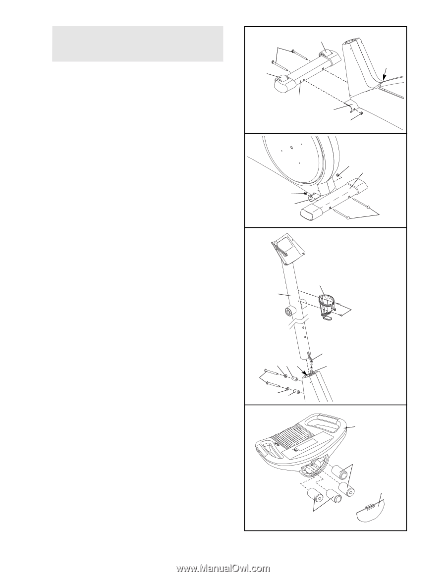
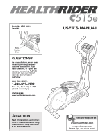
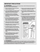
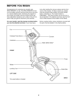
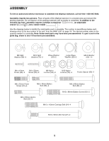
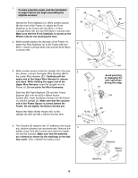
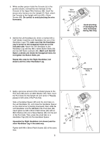
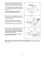
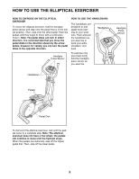
1. To make assembly easier, read the information on page 5 before you begin assembling the elliptical exerciser. Identify the Front Stabilizer (3). While another person lifts the front of the Frame (1), attach the Front Stabilizer to the Frame with two M10 x 112mm Carriage Bolts (34) and two M10 Nylon Locknuts (29). Make sure that the Front Stabilizer is turned so the Wheels (32) are not touching the floor. 2. While another person lifts the back of the Frame (1), attach the Rear Stabilizer (4) to the Frame with two M10 x 112mm Carriage Bolts (34) and two M10 Nylon Locknuts (29). 1 34 32 2 32 29 3 1 29 29 4 3. While another person holds the Upright (2) in the position shown, connect the Upper Wire Harness (86) to the Lower Wire Harness (87). Carefully pull the upper end of the Upper Wire Harness to remove any slack. While holding the upper end of the Upper Wire Harness, insert the Upright into the Frame (1). Do not pinch the Wire Harnesses. Slide two M10 Split Washers (70) and two Frame Spacers (83) onto two M10 x 88mm Button Screws (63). Insert the Button Screws into the Frame (1) and the Upright (2). Make sure that the concave end of the Frame Spacer is turned toward the Frame. Do not tighten the Button Screws yet. Attach the Water Bottle Holder (91) to the Upright (2) with two M4 x 22mm Screws (93). 4. The Console (5) requires four "D" batteries (not included); alkaline batteries are recommended. Remove the battery cover from the Console and insert four batteries into the Console. Make sure that the batteries are oriented as shown by the markings on the battery cover. Then, reattach the battery cover. 29 1 3 2 70 83 1 63 70 83 4 34 Avoid pinching or damaging the wire harnesses during this step. 91 93 86 87 5 Batteries Battery Cover Batteries 6
-
 1
1 -
 2
2 -
 3
3 -
 4
4 -
 5
5 -
 6
6 -
 7
7 -
 8
8 -
 9
9 -
 10
10 -
 11
11 -
 12
12 -
13
-
14
-
15
-
16
-
17
-
18
-
19
-
20
 |
 |