HealthRider C860e Elliptical Canadian English Manual - Page 7
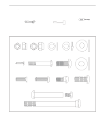
M6 x 20mm Pedal Screws 20 as shown. Note:
 |
View all HealthRider C860e Elliptical manuals
Add to My Manuals
Save this manual to your list of manuals |
Page 7 highlights
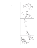
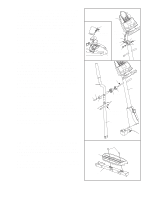
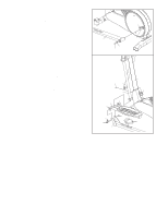
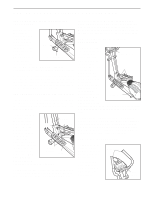
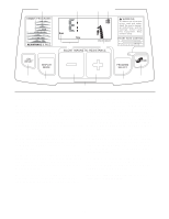
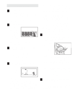
5. The Console (5) requires four "D" batteries (not included); alkaline batteries are recommended. Refer to the inset drawing. Press the tab on the battery cover, and lift off the battery cover. Insert four batteries into the battery compartment. Make sure that the batteries are oriented as shown by the diagram inside the battery compartment. Reattach the battery cover. While another person holds the Console (5) in the position shown, connect the wire harness on the Console to the Upper Wire Harness (86). Insert the excess wire harness into the Upright (2). Next, attach the Console to the Upright with three M10 x 27mm Screws (71) and three M10 Split Washers (70). Be careful to avoid pinching the wire harnesses. 6. Identify the Left Handlebar (9), which is marked with a sticker. Insert the Left Handlebar into one of the Handlebar Legs (79); make sure that the Handlebar Leg is turned so the hexagonal holes are on the indicated side. Attach the Left Handlebar to the Handlebar Leg with two M8 x 45mm Button Bolts (83) and two M8 Nylon Locknuts (46). Make sure that the Nylon Locknuts are inside of the hexagonal holes. Do not fully tighten the Button Bolts yet. Apply a small amount of the included grease to the left and right axles on the Upright (2). Carefully slide an Upright Spacer (26), a Handlebar Spacer (25), the Left Handlebar (9), and a Handlebar Cap (23) onto the left axle on the Upright (2) as shown. Slide an M10 Spacer (53) onto an M8 x 19mm Shoulder Screw (22), and tighten the Shoulder Screw into the axle. Attach the Right Handlebar and the other Handlebar Leg (not shown) in the same way. 5 5 Tab Battery Cover Batteries Wire Harness 86 71 70 71 5 6 9 53 22 23 83 Grease 26 25 46 Hexagonal Holes 79 2 71 70 2 7. Attach a Pedal (12) to the Left Pedal Arm (15) with two M6 x 20mm Pedal Screws (20) as shown. Note: The 7 20 Pedal can be attached in any of three positions (see HOW TO ADJUST THE PEDALS AND THE UPRIGHT on page 9). 12 Attach the other Pedal (not shown) to the Right Pedal Arm (not shown) in the same way. Make sure that both Pedals are attached in the same position. 15 7
-
 1
1 -
 2
2 -
 3
3 -
 4
4 -
 5
5 -
 6
6 -
 7
7 -
 8
8 -
 9
9 -
 10
10 -
 11
11 -
 12
12 -
13
-
14
-
15
-
16
-
17
-
18
-
19
-
20
-
21
-
22
-
23
-
24
 |
 |
