HP 0x2x16 HP IP and Server Console Switches G2 User Guide - Page 21
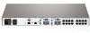
Rear panel power status LEDs, Rear panel Ethernet connection LEDs
 |
View all HP 0x2x16 manuals
Add to My Manuals
Save this manual to your list of manuals |
Page 21 highlights
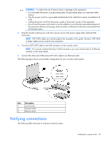
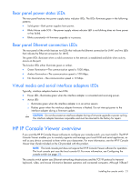
Rear panel power status LEDs The rear panel features two power supply status indicator LEDs. The LEDs illuminate green in the following patterns: • Solid green-Both power supplies have power. • Blinks Morse code SOS-The power supply whose indicator LED is not blinking does not have power or has failed. • Blinks consistently-A firmware upgrade is in process. Rear panel Ethernet connection LEDs The rear panel of the switch features two LEDs that indicate the Ethernet connection for LAN1 and two LEDs that indicate the Ethernet connection for LAN2. The green LEDs illuminate when a valid connection to the network is established and blink when activity occurs on the port. The bi-color LEDs either illuminate green or amber. • Green illumination-The communication speed is 1000 Mbps. • Amber illumination-The communication speed is 100 Mbps. • No illumination-The communication speed is 10 Mbps. Virtual media and serial interface adapters LEDs Typically, interface adapters feature two LEDs: • Power LED-Illuminates green when the interface adapter is connected and receiving power. • Active LED: o Illuminates green when the interface adapter is in an active session o Flashes green when the interface adapter firmware is flashed. Do not interrupt power to the interface adapter during a firmware update. CAUTION: Do not disconnect an interface adapter during a firmware upgrade or power cycling. The interface adapter becomes inoperable and must be returned to the factory for repair. HP IP Console Viewer overview If you want the HP IP Console Viewer software to configure your console switch, you must install it. The HP IP Console Viewer enables you to remotely organize and manage your local KVM and serial appliances, as well as any device connected to them within your datacenter. For more information, see the HP IP Console Viewer User Guide included on the CD provided with this product. NOTE: The local console port does not require the HP IP Console Viewer software for operation. The local console port uses the local console UI. For more information, see Configuring the console switch (on page 29). The console switch system uses Ethernet networking infrastructures and the TCP/IP protocol to transmit keyboard, video, and mouse information between operators and connected computers. Although 10Base-T Installing the console switch 21
-
 1
1 -
2
-
3
-
4
-
5
-
6
-
7
-
8
-
9
-
10
-
11
-
12
-
13
-
14
-
15
-
 16
16 -
 17
17 -
 18
18 -
 19
19 -
 20
20 -
 21
21 -
 22
22 -
 23
23 -
 24
24 -
 25
25 -
 26
26 -
27
-
28
-
29
-
30
-
31
-
32
-
33
-
34
-
35
-
36
-
37
-
38
-
39
-
40
-
41
-
42
-
43
-
44
-
45
-
46
-
47
-
48
-
49
-
50
-
51
-
52
-
53
-
54
-
55
-
56
-
57
-
58
-
59
-
60
-
61
-
62
-
63
-
64
-
65
-
66
-
67
-
68
-
69
-
70
-
71
-
72
-
73
-
74
-
75
-
76
-
77
-
78
-
79
-
80
-
81
-
82
-
83
 |
 |