HP 14-af100 Maintenance and Service Guide - Page 63
WLAN module see, Memory module see
 |
View all HP 14-af100 manuals
Add to My Manuals
Save this manual to your list of manuals |
Page 63 highlights
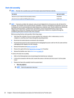
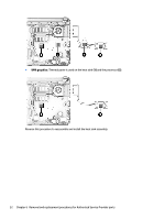
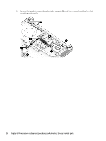
Description ● AMD A6-6310 processor ● AMD E1-6015 processor Spare part number 814508-001, -501, 601 814506-001, -501, 601 Before removing the system board, follow these steps: 1. Shut down the computer. If you are unsure whether the computer is off or in Hibernation, turn the computer on, and then shut it down through the operating system. 2. Disconnect all external devices connected to the computer. 3. Disconnect the power from the computer by first unplugging the power cord from the AC outlet and then unplugging the AC adapter from the computer. 4. Remove the battery (see Battery on page 30). 5. Remove the optical drive (see Optical drive on page 31), if installed. 6. Remove the bottom cover (see Bottom cover on page 34). 7. Remove the hard drive (see Hard drive on page 37). 8. If applicable, remove the eMMC drive (see eMMC drive on page 39). NOTE: When replacing the system board, be sure that the following components are removed from the defective system board and installed on the replacement system board: ● WLAN module (see WLAN module on page 41) ● Memory module (see Memory module on page 43) To remove the system board: 1. Remove the display and antenna cables by disconnecting the display cable from the system board (1). 2. Disconnect the antenna cable from the WLAN module (2). 3. (Touch models only) Disconnect the touch cable from the system board (3). 4. Remove the cables from the clips in the middle of the computer (4). 5. Remove the cable from the clips near the battery bay (5). Component replacement procedures 55
-
 1
1 -
2
-
3
-
4
-
5
-
6
-
7
-
8
-
9
-
10
-
11
-
12
-
13
-
14
-
15
-
16
-
17
-
18
-
19
-
20
-
21
-
22
-
23
-
24
-
25
-
26
-
27
-
28
-
29
-
30
-
31
-
32
-
33
-
34
-
35
-
36
-
37
-
38
-
39
-
40
-
41
-
42
-
43
-
44
-
45
-
46
-
47
-
48
-
49
-
50
-
51
-
52
-
53
-
54
-
55
-
56
-
57
-
 58
58 -
 59
59 -
 60
60 -
 61
61 -
 62
62 -
 63
63 -
 64
64 -
 65
65 -
 66
66 -
 67
67 -
 68
68 -
69
-
70
-
71
-
72
-
73
-
74
-
75
-
76
-
77
-
78
-
79
-
80
-
81
-
82
-
83
-
84
-
85
-
86
-
87
-
88
-
89
-
90
-
91
-
92
-
93
-
94
-
95
-
96
-
97
-
98
-
99
-
100
-
101
-
102
-
103
-
104
-
105
-
106
-
107
-
108
-
109
-
110
-
111
-
112
-
113
-
114
-
115
-
116
-
117
-
118
-
119
-
120
-
121
-
122
-
123
-
124
 |
 |