HP 15-af000 Maintenance and Service Guide
HP 15-af000 Manual
 |
View all HP 15-af000 manuals
Add to My Manuals
Save this manual to your list of manuals |
HP 15-af000 manual content summary:
- HP 15-af000 | Maintenance and Service Guide - Page 1
HP Notebook PC (AMD) HP 255 G4 Notebook PC Maintenance and Service Guide - HP 15-af000 | Maintenance and Service Guide - Page 2
and services. Nothing herein should be construed as constituting an additional warranty. HP shall not be liable for technical or editorial errors or omissions contained herein. Second Edition: August 2015 First Edition: April 2015 Document Part Number: 808736-002 Product notice This guide describes - HP 15-af000 | Maintenance and Service Guide - Page 3
Safety warning notice WARNING! To reduce the possibility of heat-related injuries or of overheating the device, do not place the device directly on your lap or obstruct the device air vents. Use the device only on a hard, flat surface. Do not allow another hard surface, such as an adjoining optional - HP 15-af000 | Maintenance and Service Guide - Page 4
iv Safety warning notice - HP 15-af000 | Maintenance and Service Guide - Page 5
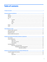
Miscellaneous parts ...22 Display assembly subcomponents ...23 4 Removal and replacement procedures preliminary requirements 25 Tools required ...25 Service considerations ...25 Plastic parts ...25 Cables and connectors ...25 Drive handling ...26 Grounding guidelines ...26 Electrostatic discharge - HP 15-af000 | Maintenance and Service Guide - Page 6
6 Removal and replacement procedures for Authorized Service Provider parts 33 Component replacement procedures ...33 Display subcomponents (bezel, webcam, panel 33 Bottom cover ...37 Optical drive board ...38 Hard drive ...40 WLAN module ... - HP 15-af000 | Maintenance and Service Guide - Page 7
specific files ...80 Restoring specific files using Windows Backup and Restore 80 Recovering the original system using HP Recovery Manager 80 What you need to know 80 Recovering using HP Recovery partition (select models only 81 Recovering using the recovery media 81 Changing the computer boot - HP 15-af000 | Maintenance and Service Guide - Page 8
boot order 93 Removing the HP Recovery partition (select products only 93 13 Using HP PC Hardware Diagnostics (UEFI) ...95 Downloading HP PC Hardware Diagnostics (UEFI) to a USB device 95 14 Specifications ...97 Computer specifications ...97 39.6-cm (15.6-in) display specifications ...98 Hard - HP 15-af000 | Maintenance and Service Guide - Page 9
Product name Processors Chipset Graphics Panel Memory Description HP Notebook PC HP 255 G4 Notebook PC AMD Dual-Core E-Series PRO) with up to 1024 MB of dedicated video memory, 18W Support HD Decode, DX11, HDMI, and PX7 39.6-cm (15.6-in), high-definition (HD), white light-emitting diode (WLED), SVA - HP 15-af000 | Maintenance and Service Guide - Page 10
-GB, 7200-rpm, 9.5-mm or 7.0-mm Fixed, serial ATA, 9.5-mm tray load DVD+/-RW Double-Layer SuperMulti Supports zero power optical drive Supports M-disc Supports configuration without optical drive HP TrueVision HD: HD camera - Fixed (no tilt) + activity LED, USB 2.0, M-JPEG, 1280 x 720 by 30 frames - HP 15-af000 | Maintenance and Service Guide - Page 11
Category Keyboard/pointing devices Power requirements Security Operating system Serviceability Description USB 3.0 (1 port; left side) touch gestures, 2-finger scrolling, and pinch-zoom enabled Taps enabled by default Support Windows 8 Modern Trackpad Gestures AC adapters: 65-W Smart nPFC, 3 pin, - HP 15-af000 | Maintenance and Service Guide - Page 12
4 Chapter 1 Product description - HP 15-af000 | Maintenance and Service Guide - Page 13
2 External component identification Display Component Description (1) Internal display switch Turns off the display and initiates Sleep if the display is closed while the power is on. NOTE: The internal display switch is not visible from the outside of the computer. (2) WLAN antenna* Send - HP 15-af000 | Maintenance and Service Guide - Page 14
Component Description To access this document in Windows 7: Select Start > HP Support Assistant > Next > My computer > User Guides. To access this document in Windows 8.1: From the Start screen, type support, and then select the HP Support Assistant app. ‒ or - From the Windows desktop, click the - HP 15-af000 | Maintenance and Service Guide - Page 15
disc compatibility information, go to the Help and Support web page. Follow the web page instructions to select your computer model. Select Drivers & Downloads, and then follow the on-screen instructions. Releases the disc tray. Attaches an optional security cable to - HP 15-af000 | Maintenance and Service Guide - Page 16
-in (microphone) Connects optional powered stereo speakers, headphones, jack earbuds, a headset, or a television audio cable. Also connects an optional headset microphone. This jack does not support optional microphone-only devices. 8 Chapter 2 External component identification - HP 15-af000 | Maintenance and Service Guide - Page 17
question mark icon in the notification area, at the far right of the taskbar. Windows 10: Select Start, select All apps, select HP Help and Support, and then select HP Documentation. NOTE: When a device is connected to the jack, the computer speakers are disabled. NOTE: Be sure that the device cable - HP 15-af000 | Maintenance and Service Guide - Page 18
Component (1) (2) (3) TouchPad zone Left TouchPad button Right TouchPad button Lights Description Reads your finger gestures to move the pointer or activate items on the screen. Functions like the left button on an external mouse. Functions like the right button on an external mouse. Component - HP 15-af000 | Maintenance and Service Guide - Page 19
Buttons Component (1) Power button Description ● When the computer is off, press the button to turn on the computer. ● When the computer is on, press the button briefly to initiate Sleep. ● When the computer is in the Sleep state, press the button briefly to exit Sleep. ● When the computer is in - HP 15-af000 | Maintenance and Service Guide - Page 20
Component Keys Description ▲ Type power in the taskbar search box, and then select Power and sleep settings. ‒ or - Right-click the Start button, and then select Power Options. Component (1) (2) (3) esc key fn key Windows key (4) Action keys (5) num lock key (6) Integrated numeric keypad - HP 15-af000 | Maintenance and Service Guide - Page 21
Bottom Component (1) Battery lock (2) Battery bay (3) Battery release latch (4) Speakers (2) Description Locks the battery in the battery bay. Holds the battery. Releases the battery. Produce sound. Bottom 13 - HP 15-af000 | Maintenance and Service Guide - Page 22
labels affixed to the computer provide information you may need when you troubleshoot system problems or travel internationally with the computer. ● Service label-Provides important information to identify your computer. When contacting support, you will probably be asked for the serial number, and - HP 15-af000 | Maintenance and Service Guide - Page 23
Windows 8)-Contains the Windows Product Key. You may need the Product Key to update or troubleshoot the operating system. HP platforms with Windows 8 or Windows 8.x preinstalled do not have the physical label. Instead countries or regions in which the devices have been approved for use. Labels 15 - HP 15-af000 | Maintenance and Service Guide - Page 24
16 Chapter 2 External component identification - HP 15-af000 | Maintenance and Service Guide - Page 25
Computer major components NOTE: HP continually improves and changes product parts. For complete and current information on supported parts for your computer, go to http://partsurfer.hp.com, select your country or region, and then follow the on-screen instructions. Computer major components 17 - HP 15-af000 | Maintenance and Service Guide - Page 26
(3) (4) Component Spare part number Display assembly (39.6-cm [15.6-in]) NOTE: For display assembly spare part information, see xxxxxx-601: Windows 8.1 Professional or Windows 10 operating system For use in HP Notebook PC models: Discrete graphics memory; Non-touch screen models: ● AMD A8 - HP 15-af000 | Maintenance and Service Guide - Page 27
-6015 processor UMA graphics memory, touch screen models: ● AMD A8-7410 processor ● AMD A6-6310 processor ● AMD A6-5200 processor For use in HP 255 G4 models: UMA graphics memory ● AMD A8-7410 processor ● AMD A6-6310 processor ● AMD E1-6015 processor (5) USB board (includes cable) (6) Memory - HP 15-af000 | Maintenance and Service Guide - Page 28
or 829319-001 for 1 TB drives. The hard drive cable is available using spare part number 830311-001. For use only in HP Notebook models: ● 1-TB, 5400-rpm, hybrid 8 GB SSD 731999-005 For use in all models: ● 1-TB, 5400-rpm, 2.5-inch 778192-005 ● 750 GB, 5400 rpm hard drive, 2.5 inch ● 500 - HP 15-af000 | Maintenance and Service Guide - Page 29
DVD+/-RW Double-Layer SuperMulti; includes bracket and bezel) For use in HP Notebook models For use in HP 255 G4 Notebook models Hard drive, SATA; does not include bracket): For use only in HP Notebook models: ● 1-TB, 5400-rpm, hybrid 8 GB SSD For use in all models: ● 1-TB, 5400-rpm, 2.5-in ● 750-GB - HP 15-af000 | Maintenance and Service Guide - Page 30
Miscellaneous parts Component HP Smart AC adapter: 65-W non-PFC EM (for use in the People's and Singapore Rubber Kit (includes front and rear feet) Screw Kit HP HDMI to VGA Adapter Notebook sleeve HP flash drive, 16 GB HP Z3600 Wireless Mouse, black Spare part number 714657-001 710412-001 741727 - HP 15-af000 | Maintenance and Service Guide - Page 31
Display assembly subcomponents Item Component (1) Display bezel (includes Mylar screw covers) For use in HP Notebook models For use in HP 255 G4 Notebook models (2) Raw display panel (39.6-cm [15.6-in], HD, WLED, BrightView) For use in models without a touch screen (BrightView) For use in - HP 15-af000 | Maintenance and Service Guide - Page 32
models with a touch screen: ● Black models ● Turbo silver models ● Red models ● White silver models ● Blue models ● Purple models ● Rose models For use in HP 255 G4 Notebook models Spare part number 813943-001 813944-001 813925-001 813930-001 813929-001 813926-001 813927-001 813928-001 831917-001 - HP 15-af000 | Maintenance and Service Guide - Page 33
plastic parts. Use care when handling the plastic parts. Apply pressure only at the points designated in the maintenance instructions. Cables and connectors CAUTION: When servicing the computer, be sure that cables are placed in their proper locations during the reassembly process. Improper cable - HP 15-af000 | Maintenance and Service Guide - Page 34
Drive handling CAUTION: Drives are fragile components that must be handled with care. To prevent damage to the computer, damage to a drive, or loss of information, observe these precautions: Before removing or inserting a hard drive, shut down the computer. If you are unsure whether the computer is - HP 15-af000 | Maintenance and Service Guide - Page 35
V 12,000 V 6,000 V 2,000 V 11,500 V 14,500 V 26,500 V 21,000 V Relative humidity 40% 15,000 V 5,000 V 800 V 700 V 4,000 V 5,000 V 20,000 V 11,000 V 55% 7,500 V 3,000 use properly grounded tools and equipment. ● Use conductive field service tools, such as cutters, screwdrivers, and vacuums. ● When - HP 15-af000 | Maintenance and Service Guide - Page 36
with ground cords of one megohm resistance ● Static-dissipative tables or floor mats with hard ties to the ground ● Field service kits ● Static awareness labels ● Material-handling packages ● Nonconductive plastic bags, tubes, or boxes ● Metal tote boxes ● Electrostatic voltage levels and - HP 15-af000 | Maintenance and Service Guide - Page 37
on supported parts for your computer, go to http://partsurfer.hp.com, select your country or region, and then follow the on-screen instructions. many as 3 screws that must be removed, replaced, or loosened when servicing Customer SelfRepair parts. Make special note of each screw size and location - HP 15-af000 | Maintenance and Service Guide - Page 38
Battery Description 4-cell, 41-Whr, 2.8-Ah Li-ion battery 3-cell, 31-Whr, 2.8-Ah Li-ion battery Spare part number 807957-001 807956-001 Before disassembling the computer, follow these steps: 1. Shut down the computer. If you are unsure whether the computer is off or in Hibernation, turn the - HP 15-af000 | Maintenance and Service Guide - Page 39
part kits include bracket and bezel. Description DVD+/-RW Double-Layer SuperMulti Drive for use in HP Notebook models (includes bracket and bezel) DVD+/-RW Double-Layer SuperMulti Drive for use in HP 255 G4 Notebook models (includes bracket and bezel) Spare part number 813952-001 814617-001 Before - HP 15-af000 | Maintenance and Service Guide - Page 40
32 Chapter 5 Removal and replacement procedures for Customer Self-Repair parts - HP 15-af000 | Maintenance and Service Guide - Page 41
supported parts for your computer, go to http://partsurfer.hp.com, select your country or region, and then follow the on-screen instructions as 56 screws that must be removed, replaced, or loosened when servicing Authorized Service Provider only parts. Make special note of each screw size and - HP 15-af000 | Maintenance and Service Guide - Page 42
module: a. Position the display assembly with the top edge toward you. b. Disconnect the cable (1) from the module. 34 Chapter 6 Removal and replacement procedures for Authorized Service Provider parts - HP 15-af000 | Maintenance and Service Guide - Page 43
c. Lift to disengage the adhesive that secures the webcam/microphone module to the display, and then remove the module (2). 5. To remove the display panel: a. Remove the four Phillips PM2.0×2.4 screws (1) that secure the display panel to the enclosure. b. Rotate the display panel onto the keyboard - HP 15-af000 | Maintenance and Service Guide - Page 44
d. Remove the display panel from the computer (3). Reverse this procedure to reassemble and install the display bezel, webcam/microphone module, and display panel. 36 Chapter 6 Removal and replacement procedures for Authorized Service Provider parts - HP 15-af000 | Maintenance and Service Guide - Page 45
Notebook models: ● With an optical drive ● Without an optical drive For use in HP 255 G4 Notebook models: ● With an optical drive ● Without an optical drive Spare part number 813937-001 813939-001 814614-001 816606-001 Before removing - HP 15-af000 | Maintenance and Service Guide - Page 46
the system board (1). 2. Remove the Phillips PM2.0×2.4 screw (2) that secures the optical drive board to the computer. 38 Chapter 6 Removal and replacement procedures for Authorized Service Provider parts - HP 15-af000 | Maintenance and Service Guide - Page 47
3. Remove the board and cable from the computer (3). Reverse this procedure to install the optical drive board and cable. Component replacement procedures 39 - HP 15-af000 | Maintenance and Service Guide - Page 48
spare part kit does not include the hard drive bracket. Description For use only in HP Notebook models: 1-TB, 5400-rpm, hybrid 8 GB SSD For use in all models: 1-TB, 5400-rpm, 2.5-in 750 GB, 5400 rpm the computer. 40 Chapter 6 Removal and replacement procedures for Authorized Service Provider parts - HP 15-af000 | Maintenance and Service Guide - Page 49
3. Lift the hard drive assembly from the computer (3). 4. To disassemble the hard drive, pull the connector away from the drive to remove it (1). 5. To remove the hard drive brackets, remove the two Phillips PM3.0×3.0 screws (2) that secure each bracket to the hard drive. 6. Remove the hard drive - HP 15-af000 | Maintenance and Service Guide - Page 50
and then receive a warning message, remove the module to restore device functionality, and then contact support. Before removing the WLAN module, follow these steps: 1. Shut down the computer. If you are up.) 42 Chapter 6 Removal and replacement procedures for Authorized Service Provider parts - HP 15-af000 | Maintenance and Service Guide - Page 51
3. Remove the WLAN module by pulling the module away from the slot at an angle (3). NOTE: If the WLAN antennas are not connected to the terminals on the WLAN module, the protective sleeves must be installed on the antenna connectors, as shown in the following illustration. Reverse this procedure to - HP 15-af000 | Maintenance and Service Guide - Page 52
(2) by pulling it away from the slot at an angle. Reverse this procedure to install a memory module. 44 Chapter 6 Removal and replacement procedures for Authorized Service Provider parts - HP 15-af000 | Maintenance and Service Guide - Page 53
RTC battery Description RTC battery Spare part number 759981-001 Before removing the RTC battery, follow these steps: 1. Shut down the computer. If you are unsure whether the computer is off or in Hibernation, turn the computer on, and then shut it down through the operating system. 2. Disconnect - HP 15-af000 | Maintenance and Service Guide - Page 54
to the computer. 4. Remove the USB board and cable (4). Reverse this procedure to install the USB board. 46 Chapter 6 Removal and replacement procedures for Authorized Service Provider parts - HP 15-af000 | Maintenance and Service Guide - Page 55
Speakers Description Speakers (includes left and right speakers and cable) Spare part number 813965-001 Before removing the speakers, follow these steps: 1. Shut down the computer. If you are unsure whether the computer is off or in Hibernation, turn the computer on, and then shut it down through - HP 15-af000 | Maintenance and Service Guide - Page 56
installing the speakers, make sure the gaskets are installed correctly. Reverse this procedure to install the speakers. 48 Chapter 6 Removal and replacement procedures for Authorized Service Provider parts - HP 15-af000 | Maintenance and Service Guide - Page 57
Heat sink assembly NOTE: The heat sink assembly spare part kit includes replacement thermal materials. Description Heat sink for use in models with discrete graphics memory Heat sink for use in models with UMA Spare part number 813948-001 813947-001 NOTE: To properly ventilate the computer, allow - HP 15-af000 | Maintenance and Service Guide - Page 58
processor and associated heat sink area (1)(2), as well as the graphics chip and associated heat sink area (3)(4). 50 Chapter 6 Removal and replacement procedures for Authorized Service Provider parts - HP 15-af000 | Maintenance and Service Guide - Page 59
● UMA graphics: Thermal paste is used on the heat sink (1) and the processor (2). Reverse this procedure to reassemble and install the heat sink assembly. Component replacement procedures 51 - HP 15-af000 | Maintenance and Service Guide - Page 60
(1) from the system board. 2. Remove the two Phillips PM2.5×6.0 screws (2) that secure the fan to the computer. 52 Chapter 6 Removal and replacement procedures for Authorized Service Provider parts - HP 15-af000 | Maintenance and Service Guide - Page 61
3. Remove the fan from the computer (3). Reverse this procedure to install the fan. Component replacement procedures 53 - HP 15-af000 | Maintenance and Service Guide - Page 62
then remove the TouchPad and cables (5). Reverse this procedure to install the TouchPad button board and cables. 54 Chapter 6 Removal and replacement procedures for Authorized Service Provider parts - HP 15-af000 | Maintenance and Service Guide - Page 63
● AMD E1-6015 processor UMA graphics memory, touch screen models: ● AMD A8-7410 processor ● AMD A6-6310 processor ● AMD A6-5200 processor For use in HP 255 G4 models: UMA graphics memory ● AMD A8-7410 processor ● AMD A6-6310 processor ● AMD E1-6015 processor Spare part number 813971-001, -501, -601 - HP 15-af000 | Maintenance and Service Guide - Page 64
(3): Keyboard cable (4): Power connector cable (5): Display cable (6): Power button board cable (7): TouchPad button board cable (8): Speaker cable 56 Chapter 6 Removal and replacement procedures for Authorized Service Provider parts - HP 15-af000 | Maintenance and Service Guide - Page 65
2. Remove the six Phillips PM2.5×2.5 screws (1) that secure the system board to the computer. 3. Lift the side of the system board (2), and then pull the board away from the computer (3). Reverse this procedure to install the system board. Component replacement procedures 57 - HP 15-af000 | Maintenance and Service Guide - Page 66
display assembly from the computer. Description Raw display panel (39.6-cm [15.6-in], HD, WLED, BrightView) For use in models without a models Blue models Purple models Rose models Display enclosure for use in HP 255 G4 Notebook models Hinges (left and right) Webcam/microphone Service Provider parts - HP 15-af000 | Maintenance and Service Guide - Page 67
Description For use in HP Notebook models For use in HP 255 G4 Notebook models Spare part number 813972-001 814613-001 Before removing the display assembly, follow these steps: 1. Shut down the computer. If you - HP 15-af000 | Maintenance and Service Guide - Page 68
edges (2), and the bottom edge (3) of the display bezel until the bezel disengages from the display enclosure. 60 Chapter 6 Removal and replacement procedures for Authorized Service Provider parts - HP 15-af000 | Maintenance and Service Guide - Page 69
b. Remove the display bezel (4). NOTE: In this procedure, the display will NOT be connected to the computer, as shown in the following image. 2. To remove the webcam/microphone module: a. Position the display assembly with the top edge toward you. b. Disconnect the cable (1) from the module. - HP 15-af000 | Maintenance and Service Guide - Page 70
this procedure, the display will NOT be connected to the computer, as shown in the following image. 62 Chapter 6 Removal and replacement procedures for Authorized Service Provider parts - HP 15-af000 | Maintenance and Service Guide - Page 71
c. On the back of the display panel, release the adhesive strip (1) that secures the display panel cable to the display panel, and then disconnect the cable (2). d. Remove the display panel from the computer (3). NOTE: In this procedure, the display will NOT be connected to the computer, as shown in - HP 15-af000 | Maintenance and Service Guide - Page 72
b. Remove the display hinges (2). 5. To remove the wireless antenna cables and transceivers, release the wireless antenna cables from the clips built into the display enclosure (1), and then remove the cables (2). 64 Chapter 6 Removal and replacement procedures for Authorized Service Provider parts - HP 15-af000 | Maintenance and Service Guide - Page 73
6. To remove the display/webcam cable, remove the cable from the clips built into the display enclosure (1), and then remove the cable from the display enclosure (2). 7. If replacing the display enclosure, be sure that the subcomponents (including the webcam/microphone module, the antenna receivers, - HP 15-af000 | Maintenance and Service Guide - Page 74
to the computer (1). 2. Remove the power connector cable (2). Reverse this procedure to install the power connector cable. 66 Chapter 6 Removal and replacement procedures for Authorized Service Provider parts - HP 15-af000 | Maintenance and Service Guide - Page 75
Power button board Description Power button board (includes cable) Spare part number 813955-001 Before removing the power button board, follow these steps: 1. Shut down the computer. If you are unsure whether the computer is off or in Hibernation, turn the computer on, and then shut it down - HP 15-af000 | Maintenance and Service Guide - Page 76
68 Chapter 6 Removal and replacement procedures for Authorized Service Provider parts - HP 15-af000 | Maintenance and Service Guide - Page 77
HP website. Most BIOS updates on the HP website are packaged in compressed files called SoftPaqs. Some download packages contain a file named Readme.txt, which contains information regarding installing and troubleshooting download and installation, follow these instructions: Do not disconnect power - HP 15-af000 | Maintenance and Service Guide - Page 78
Select Start, type hp support assistant, and then select the HP Support Assistant program. 2. Follow the on-screen instructions to identify your computer it has been downloaded to your hard drive. b. Follow the on-screen instructions to download your selection to the hard drive. Make a note of the - HP 15-af000 | Maintenance and Service Guide - Page 79
HP website. Most BIOS updates on the HP website are packaged in compressed files called SoftPaqs. Some download packages contain a file named Readme.txt, which contains information regarding installing and troubleshooting support, selecting the HP Support , follow these instructions: ● Do - HP 15-af000 | Maintenance and Service Guide - Page 80
and then select the HP Support Assistant app. ‒ or - From the Windows desktop, click the question mark icon in the notification area, at the far right of the taskbar. 2. Click Updates and tune-ups, and then click Check for HP updates now. 3. Follow the on-screen instructions. 4. At the download area - HP 15-af000 | Maintenance and Service Guide - Page 81
(BIOS) may be available on the HP website. Most BIOS updates on the HP website are packaged in compressed files called SoftPaqs. Some download packages contain a file named Readme.txt, which contains information regarding installing and troubleshooting the file. Determining the BIOS version To - HP 15-af000 | Maintenance and Service Guide - Page 82
in the taskbar search box, and then select the HP Support Assistant app. - or - Click the question mark icon in the taskbar. 2. Click Updates, and then click Check for updates and messages. 3. Follow the on-screen instructions. 4. At the download area, follow these steps: a. Identify the most - HP 15-af000 | Maintenance and Service Guide - Page 83
that has an .exe extension (for example, filename.exe). The BIOS installation begins. 5. Complete the installation by following the on-screen instructions. NOTE: After a message on the screen reports a successful installation, you can delete the downloaded file from your hard drive. Synchronizing - HP 15-af000 | Maintenance and Service Guide - Page 84
76 Chapter 9 Using Setup Utility (BIOS) in Windows 10 - HP 15-af000 | Maintenance and Service Guide - Page 85
these recovery tools carefully, and keep them in a safe place. ● HP Recovery Manager examines the computer and determines the required storage capacity for the discs, or you can obtain recovery discs for your computer from the HP website. If you use an external optical drive, it must be connected - HP 15-af000 | Maintenance and Service Guide - Page 86
Creation. 3. Follow the on-screen instructions to continue. To recover, see Recovering the original system using HP Recovery Manager on page 80. . For more information about using shadow copies to restore, see Help and Support. Creating a system restore point 1. Select Start > Control Panel > System - HP 15-af000 | Maintenance and Service Guide - Page 87
> System and Security > Backup and Restore. 2. Follow the on-screen instructions to schedule and create a backup. NOTE: Windows includes the User Account Control running utilities, or changing Windows settings. See Help and Support for more information. To restore, see Restoring specific files using - HP 15-af000 | Maintenance and Service Guide - Page 88
software fixes the problems. If uninstalling does not fix the problems, you can Click System Restore, and follow the on-screen instructions. Restoring specific files If files are accidentally deleted from Support for more information. Recovering the original system using HP Recovery Manager HP - HP 15-af000 | Maintenance and Service Guide - Page 89
press f11 while the "F11 (System Recovery)" message is displayed on the screen. 2. Click System Recovery in the HP Recovery Manager window. 3. Follow the on-screen instructions. Recovering using the recovery media 1. If possible, back up all personal files. 2. Insert the first recovery disc into - HP 15-af000 | Maintenance and Service Guide - Page 90
1. Insert the flash drive into a USB port. 2. Restart the computer. 3. Press esc while the computer is restarting, and then press f9 for boot options. 4. Select the flash drive from the boot options window. 82 Chapter 10 Backing up, restoring, and recovering in Windows 7 - HP 15-af000 | Maintenance and Service Guide - Page 91
Numbers booklet included with the computer. You can also find contact information from the HP website. Go to http://www.hp.com/support, select your country or region, and follow the on-screen instructions. HP Recovery Manager is a software program that allows you to create recovery media after you - HP 15-af000 | Maintenance and Service Guide - Page 92
Telephone Numbers booklet included with the computer. You can also find contact information from the HP website. Go to http://www.hp.com/support, select your country or region, and follow the on-screen instructions. If you use an external optical drive, it must be connected directly to a USB port - HP 15-af000 | Maintenance and Service Guide - Page 93
▲ From the Start screen, type support, and then select the HP Support Assistant app. - or - From the Windows desktop, click the question mark icon in the notification area, at the far right of the taskbar. ● If you need to correct a problem with a preinstalled application or driver, use the Drivers - HP 15-af000 | Maintenance and Service Guide - Page 94
or press and hold f11 as you press the power button. 2. Select Troubleshoot from the boot options menu. 3. Select Recovery Manager, and then follow the on-screen instructions. Using HP Recovery media to recover You can use HP Recovery media to recover the original system. This method can be used if - HP 15-af000 | Maintenance and Service Guide - Page 95
the optical drive or USB flash drive from which you want to boot. 4. Follow the on-screen instructions. Removing the HP Recovery partition (select models only) HP Recovery Manager software allows you to remove the HP Recovery partition to free up hard drive space. IMPORTANT: After you remove the - HP 15-af000 | Maintenance and Service Guide - Page 96
88 Chapter 11 Backing up, restoring, and recovering in Windows 8.1 - HP 15-af000 | Maintenance and Service Guide - Page 97
media for your system from support. See the Worldwide Telephone Numbers booklet included with the computer. You can also find contact information on the HP website. Go to http://www.hp.com/support, select your country or region, and follow the on-screen instructions. Creating recovery media and - HP 15-af000 | Maintenance and Service Guide - Page 98
Telephone Numbers booklet included with the computer. You can also find contact information on the HP website. Go to http://www.hp.com/ support, select your country or region, and follow the on-screen instructions. ◦ Be sure that the computer is connected to AC power before you begin creating the - HP 15-af000 | Maintenance and Service Guide - Page 99
search box, select HP Recovery Manager, select Reinstall drivers and/or applications, and then follow the on-screen instructions. ● If you the creation of HP Recovery media or if the HP Recovery media does not work, you can obtain recovery media for your system from support. See the Worldwide - HP 15-af000 | Maintenance and Service Guide - Page 100
then quickly hold down the Windows button; then select f11. 2. Select Troubleshoot from the boot options menu. 3. Select Recovery Manager, and then follow the on-screen instructions. Using HP Recovery media to recover You can use HP Recovery media to recover the original system. This method can be - HP 15-af000 | Maintenance and Service Guide - Page 101
is only available on products that support this function. Follow these steps to remove the HP Recovery partition: 1. Type recovery in the taskbar search box, and then select HP Recovery Manager. 2. Select Remove Recovery Partition, and then follow the on-screen instructions. Restore and recovery 93 - HP 15-af000 | Maintenance and Service Guide - Page 102
94 Chapter 12 Backing up, restoring, and recovering in Windows 10 - HP 15-af000 | Maintenance and Service Guide - Page 103
instructions. NOTE: If you need to stop a diagnostic test, press or tap esc. Downloading HP PC Hardware Diagnostics (UEFI) to a USB device NOTE: Instructions for downloading HP : 1. Go to http://www.hp.com/support, and then select your country. The HP Support page is displayed. 2. Click Drivers - HP 15-af000 | Maintenance and Service Guide - Page 104
96 Chapter 13 Using HP PC Hardware Diagnostics (UEFI) - HP 15-af000 | Maintenance and Service Guide - Page 105
noncondensing) ‑20°C to 60°C ‑4°F to 140°F Operating 10% to 90% Nonoperating 5% to 95% Maximum altitude (unpressurized) Operating ‑15 m to 3,048 m ‑50 ft to 10,000 ft Nonoperating ‑15 m to 12,192 m ‑50 ft to 40,000 ft NOTE: Applicable product safety standards specify thermal limits for - HP 15-af000 | Maintenance and Service Guide - Page 106
eDP 3.2 mm (touch) 3.8 mm (non-touch) U.S. 15.6-in Hard drive specifications, hybrid drives 1000-GB*, 8 GB NAND hybrid SSD Dimensions Height 5 mm Length 100.2 mm Width 69.9 mm Certain restrictions and exclusions apply. Contact technical support for details. 98 Chapter 14 Specifications - HP 15-af000 | Maintenance and Service Guide - Page 107
*1 GB = 1 billion bytes when referring to hard drive storage capacity. Actual accessible capacity is less. NOTE: Certain restrictions and exclusions apply. Contact technical support for details. 500-GB* 7.0 mm or 9.5 mm 100.6 mm 70.1 mm 92.0 g SATA 300 MB/sec ATA security 3 ms 13 ms 24 ms - HP 15-af000 | Maintenance and Service Guide - Page 108
+R, DVD+RW, DVD-RAM Write: CD-R and CD-RW DVD+R, DVD+RW, DVD-R, DVD-RW, DVD-RAM 1.5 cm (0.59 in) 12 cm (4.72 in) 8 cm (3.15 in) 1.2 mm (0.047 in) 0.74 µm CD < 175 ms < 285 ms Line-out, 0.7 Vrms 2 MB DVD < 230 ms < 335 ms 3,600 KB/sec 10,800 KB - HP 15-af000 | Maintenance and Service Guide - Page 109
in Intel-based and AMD-based system boards. Some of these steps are disclosed in the Maintenance & Service Guides available for HP PC products available on the product support pages at www.hp.com. 1. Follow steps (a) through (I) below to restore the nonvolatile memory that can contain personal data - HP 15-af000 | Maintenance and Service Guide - Page 110
Computrace® management and tracking service was activated on the notebook contents by using the HP Disk Sanitizer® utility or a third party approved. To run HP Disk Sanitizer, enter BIOS . b. Solid State Drive (SSD) Clear the SSD contents by using the BIOS erase data from an SSD. To run Secure - HP 15-af000 | Maintenance and Service Guide - Page 111
BIOS is memory and is mouse, & updated. available on the HP battery website. Writing data management). to this ROM in an inappropriate memory and is configuration when the system BIOS is available on the HP data. updated. Configuration website. Writing data data and settings are to - HP 15-af000 | Maintenance and Service Guide - Page 112
memory and is typically not made available to the public unless a firmware upgrade is necessary to address a unique issue. Stores fingerprint templates. By enrolling in HP ProtectTools Security Manager. Only a digitally signed application can make the call to write to the flash. 104 Chapter - HP 15-af000 | Maintenance and Service Guide - Page 113
the computer and press F10 when prompted near the bottom of the display. b. Select File, then select Restore defaults. c. Follow the on-screen instructions. d. Select File, save changes and exit, then press Enter. 2. What kind of configuration data is stored on the DIMM Serial Presence Detect (SPD - HP 15-af000 | Maintenance and Service Guide - Page 114
106 Chapter 15 Statement of Volatility - HP 15-af000 | Maintenance and Service Guide - Page 115
16 Power cord set requirements The wide-range input feature of the computer permits it to operate from any line voltage from 100 to 120 volts ac, or from 220 to 240 volts ac. The 3-conductor power cord set included with the computer meets the requirements for use in the country or region where the - HP 15-af000 | Maintenance and Service Guide - Page 116
must be Type SVT/SJT or equivalent, No. 18 AWG, 3-conductor. The wall plug must be a two-pole grounding type with a NEMA 5-15P (15 A, 125 V ac) or NEMA 6-15P (15 A, 250 V ac) configuration. CSA or C-UL mark. UL file number must be on each element. 108 Chapter 16 Power cord set requirements - HP 15-af000 | Maintenance and Service Guide - Page 117
plug) must bear the BSMI certification mark. 7. For 127 V ac, the flexible cord must be Type SVT or SJT 3 x 18 AWG, with plug NEMA 5-15P (15 A, 125 V ac), with UL and CSA or CUL marks. For 240 V ac, the flexible cord must be Type H05VV-F 3X0.75/1.00mm2 conductor size, with - HP 15-af000 | Maintenance and Service Guide - Page 118
110 Chapter 16 Power cord set requirements - HP 15-af000 | Maintenance and Service Guide - Page 119
dispose of the battery in general household waste. Follow the local laws and regulations in your area for battery disposal. HP encourages customers to recycle used electronic hardware, HP original print cartridges, and rechargeable batteries. For more information about recycling programs, see the - HP 15-af000 | Maintenance and Service Guide - Page 120
112 Chapter 17 Recycling - HP 15-af000 | Maintenance and Service Guide - Page 121
15 boot order changing 81, 86, 93 bottom 15 bottom cover illustrated 20, 37 removing 37 buttons left TouchPad 10 power 11 right TouchPad 10 C cables, service removing 35, 62, 63 HP PC Hardware Diagnostics (UEFI) downloading 95 HP Recovery Manager 80 correcting boot problems 86, 93 starting 86, 92 - HP 15-af000 | Maintenance and Service Guide - Page 122
media creating 83, 89 recovery 86, 92 HP Recovery partition recovery 86, 92 removing 87, 93 I integrated 12 Windows 12 L labels Bluetooth 15 Microsoft Certificate of Authenticity 15 regulatory 15 serial number 14 service 14 wireless certification 15 WLAN 15 latch, battery release 13 lights AC - HP 15-af000 | Maintenance and Service Guide - Page 123
supported discs 84, 90 system 85, 91 USB flash drive 86, 92 using HP Recovery media 84, 90 recovery discs 77 recovery media 77 creating 83, 89 creating using HP Recovery Manager 84, 90 recovery partition removing 87, 93 recovery, system 80 regulatory information regulatory label 15 wireless - HP 15-af000 | Maintenance and Service Guide - Page 124
116 Index
-
 1
1 -
 2
2 -
 3
3 -
 4
4 -
 5
5 -
 6
6 -
 7
7 -
8
-
9
-
10
-
11
-
12
-
13
-
14
-
15
-
16
-
17
-
18
-
19
-
20
-
21
-
22
-
23
-
24
-
25
-
26
-
27
-
28
-
29
-
30
-
31
-
32
-
33
-
34
-
35
-
36
-
37
-
38
-
39
-
40
-
41
-
42
-
43
-
44
-
45
-
46
-
47
-
48
-
49
-
50
-
51
-
52
-
53
-
54
-
55
-
56
-
57
-
58
-
59
-
60
-
61
-
62
-
63
-
64
-
65
-
66
-
67
-
68
-
69
-
70
-
71
-
72
-
73
-
74
-
75
-
76
-
77
-
78
-
79
-
80
-
81
-
82
-
83
-
84
-
85
-
86
-
87
-
88
-
89
-
90
-
91
-
92
-
93
-
94
-
95
-
96
-
97
-
98
-
99
-
100
-
101
-
102
-
103
-
104
-
105
-
106
-
107
-
108
-
109
-
110
-
111
-
112
-
113
-
114
-
115
-
116
-
117
-
118
-
119
-
120
-
121
-
122
-
123
-
124
 |
 |

HP Notebook PC (AMD)
HP 255 G4 Notebook PC
Maintenance and Service Guide