HP 15-f001xx User Guide - Page 23
Bottom
 |
View all HP 15-f001xx manuals
Add to My Manuals
Save this manual to your list of manuals |
Page 23 highlights
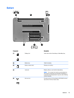
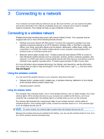
Bottom Component (1) Battery lock (2) Battery bay (3) Battery release latch (4) Vents (6) (5) Service door Description Locks and unlocks the battery in the battery bay. Holds the battery. Releases the battery. Enable airflow to cool internal components. NOTE: The computer fan starts up automatically to cool internal components and prevent overheating. It is normal for the internal fan to cycle on and off during routine operation. Provides access to the wireless LAN (WLAN) module slot and the memory module slots. Bottom 13
-
 1
1 -
2
-
3
-
4
-
5
-
6
-
7
-
8
-
9
-
10
-
11
-
12
-
13
-
14
-
15
-
16
-
17
-
 18
18 -
 19
19 -
 20
20 -
 21
21 -
 22
22 -
 23
23 -
 24
24 -
 25
25 -
 26
26 -
 27
27 -
 28
28 -
29
-
30
-
31
-
32
-
33
-
34
-
35
-
36
-
37
-
38
-
39
-
40
-
41
-
42
-
43
-
44
-
45
-
46
-
47
-
48
-
49
-
50
-
51
-
52
-
53
-
54
-
55
-
56
-
57
-
58
-
59
-
60
-
61
-
62
-
63
-
64
-
65
-
66
-
67
-
68
-
69
-
70
-
71
-
72
-
73
 |
 |

Bottom
Component
Description
(1)
Battery lock
Locks and unlocks the battery in the battery bay.
(2)
Battery bay
Holds the battery.
(3)
Battery release latch
Releases the battery.
(4)
Vents (6)
Enable airflow to cool internal components.
NOTE:
The computer fan starts up automatically to
cool internal components and prevent overheating. It
is normal for the internal fan to cycle on and off during
routine operation.
(5)
Service door
Provides access to the wireless LAN (WLAN) module
slot and the memory module slots.
Bottom
13