HP 15-f039wm HP 15 Notebook PC Maintenance and Service Guide - Page 81
that secure the hinges to, Remove the four Phillips M2.5×4.0 screws
 |
View all HP 15-f039wm manuals
Add to My Manuals
Save this manual to your list of manuals |
Page 81 highlights
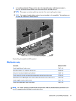
b. Detach the webcamera/microphone module (2) from the display enclosure. 6. If it is necessary to replace the hinges: a. Remove the four Phillips M2.5×4.0 screws (1) and (2) that secure the hinges to the display enclosure. b. Remove the display hinge covers (2). c. Remove the hinges and brackets (3) from the display enclosure. 7. If it is necessary to replace the display panel cable: a. Release the display panel cable from the clips (1) and routing channel built into the display enclosure. Component replacement procedures 71
-
 1
1 -
2
-
3
-
4
-
5
-
6
-
7
-
8
-
9
-
10
-
11
-
12
-
13
-
14
-
15
-
16
-
17
-
18
-
19
-
20
-
21
-
22
-
23
-
24
-
25
-
26
-
27
-
28
-
29
-
30
-
31
-
32
-
33
-
34
-
35
-
36
-
37
-
38
-
39
-
40
-
41
-
42
-
43
-
44
-
45
-
46
-
47
-
48
-
49
-
50
-
51
-
52
-
53
-
54
-
55
-
56
-
57
-
58
-
59
-
60
-
61
-
62
-
63
-
64
-
65
-
66
-
67
-
68
-
69
-
70
-
71
-
72
-
73
-
74
-
75
-
 76
76 -
 77
77 -
 78
78 -
 79
79 -
 80
80 -
 81
81 -
 82
82 -
 83
83 -
 84
84 -
 85
85 -
 86
86 -
87
-
88
-
89
-
90
-
91
-
92
-
93
-
94
-
95
-
96
-
97
 |
 |

b.
Detach the webcamera/microphone module
(2)
from the display enclosure.
6.
If it is necessary to replace the hinges:
a.
Remove the four Phillips M2.5×4.0 screws
(1)
and
(2)
that secure the hinges to
the display enclosure.
b.
Remove the display hinge covers
(2)
.
c.
Remove the hinges and brackets
(3)
from the display enclosure.
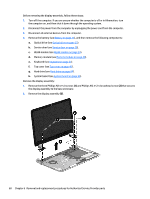
7.
If it is necessary to replace the display panel cable:
a.
Release the display panel cable from the clips
(1)
and routing channel built into the
display enclosure.
Component replacement procedures
71