HP 15-g039wm HP 15 TouchSmart Notebook PC HP 15 Notebook PC Compaq 15 TouchSma - Page 80
CAUTION, Flex the inside of the top edge
 |
View all HP 15-g039wm manuals
Add to My Manuals
Save this manual to your list of manuals |
Page 80 highlights
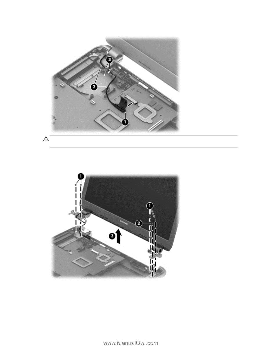
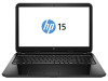
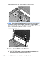
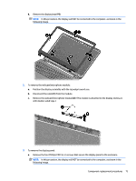
3. Release the wireless antenna cables from the clips (3) built into the base enclosure. CAUTION: Support the display assembly when removing the following screws. Failure to support the display assembly can result in damage to the display assembly and other computer components. 4. Remove the four Phillips PM2.5×5.0 screws (1) (two from each hinge) and one Phillips PM2.5×3.5 screw (2) (on the right hinge) that secures the display assembly to the computer. 5. Remove the display assembly (3). If it is necessary to replace any of the display assembly subcomponents: 1. To remove the display bezel: a. Flex the inside of the top edge (1), the left and right edges (2), and the bottom edge (3) of the display bezel until the bezel disengages from the display enclosure. 72 Chapter 6 Removal and replacement procedures for Authorized Service Provider parts
-
 1
1 -
2
-
3
-
4
-
5
-
6
-
7
-
8
-
9
-
10
-
11
-
12
-
13
-
14
-
15
-
16
-
17
-
18
-
19
-
20
-
21
-
22
-
23
-
24
-
25
-
26
-
27
-
28
-
29
-
30
-
31
-
32
-
33
-
34
-
35
-
36
-
37
-
38
-
39
-
40
-
41
-
42
-
43
-
44
-
45
-
46
-
47
-
48
-
49
-
50
-
51
-
52
-
53
-
54
-
55
-
56
-
57
-
58
-
59
-
60
-
61
-
62
-
63
-
64
-
65
-
66
-
67
-
68
-
69
-
70
-
71
-
72
-
73
-
74
-
 75
75 -
 76
76 -
 77
77 -
 78
78 -
 79
79 -
 80
80 -
 81
81 -
 82
82 -
 83
83 -
 84
84 -
 85
85 -
86
-
87
-
88
-
89
-
90
-
91
-
92
-
93
-
94
-
95
-
96
-
97
-
98
-
99
-
100
-
101
-
102
-
103
-
104
-
105
-
106
-
107
-
108
-
109
-
110
-
111
-
112
-
113
-
114
-
115
-
116
-
117
-
118
-
119
-
120
-
121
-
122
 |
 |