HP 15-g041cy HP 15 TouchSmart Notebook PC HP 15 Notebook PC Compaq 15 TouchSma - Page 69
Power connector cable, Position the computer upright
 |
View all HP 15-g041cy manuals
Add to My Manuals
Save this manual to your list of manuals |
Page 69 highlights
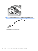
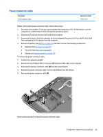
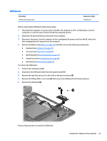
3. Disconnect the power from the computer by first unplugging the power cord from the AC outlet and then unplugging the AC adapter from the computer. 4. Remove the battery (see Battery on page 35). 5. Remove the following components: ● Keyboard (see Keyboard on page 39) ● Top cover (see Top cover on page 47) ● WLAN module (see WLAN module on page 55) ● Hard drive (see Hard drive on page 53) NOTE: When replacing the system board, be sure that the following components are removed from the defective system board and installed on the replacement system board: ● Memory module (see Memory module on page 69) ● Heat sink assembly (see Heat sink assembly on page 65) To remove the system board: 1. Position the computer upright, and then disconnect the following cables from the system board: (1): Power connector cable (2): Speaker cable (3): Fan cable (4): Display cable 2. Remove the two Phillips PM2.5×5.0 screws (5) that secure the system board to the computer. Component replacement procedures 61
-
 1
1 -
2
-
3
-
4
-
5
-
6
-
7
-
8
-
9
-
10
-
11
-
12
-
13
-
14
-
15
-
16
-
17
-
18
-
19
-
20
-
21
-
22
-
23
-
24
-
25
-
26
-
27
-
28
-
29
-
30
-
31
-
32
-
33
-
34
-
35
-
36
-
37
-
38
-
39
-
40
-
41
-
42
-
43
-
44
-
45
-
46
-
47
-
48
-
49
-
50
-
51
-
52
-
53
-
54
-
55
-
56
-
57
-
58
-
59
-
60
-
61
-
62
-
63
-
 64
64 -
 65
65 -
 66
66 -
 67
67 -
 68
68 -
 69
69 -
 70
70 -
 71
71 -
 72
72 -
 73
73 -
 74
74 -
75
-
76
-
77
-
78
-
79
-
80
-
81
-
82
-
83
-
84
-
85
-
86
-
87
-
88
-
89
-
90
-
91
-
92
-
93
-
94
-
95
-
96
-
97
-
98
-
99
-
100
-
101
-
102
-
103
-
104
-
105
-
106
-
107
-
108
-
109
-
110
-
111
-
112
-
113
-
114
-
115
-
116
-
117
-
118
-
119
-
120
-
121
-
122
 |
 |