HP 15-g042ds HP 15 TouchSmart Notebook PC HP 15 Notebook PC Compaq 15 TouchSma - Page 82
following image., In this procedure, the display will NOT be connected to the computer
 |
View all HP 15-g042ds manuals
Add to My Manuals
Save this manual to your list of manuals |
Page 82 highlights
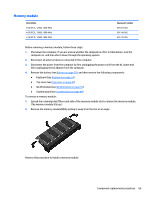
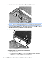
b. Rotate the display panel onto the keyboard to gain access to the display cable connection on the back of the panel (1). c. On the back of the display panel, release the adhesive strip (2) that secures the display panel cable to the display panel, and then disconnect the cable (3). NOTE: In this procedure, the display will NOT be connected to the computer, as shown in the following image. 4. To remove the display hinges: a. Remove the eight Phillips PM2.5×3.5 screws (1) that secure the display hinges to the display panel. 74 Chapter 6 Removal and replacement procedures for Authorized Service Provider parts
-
 1
1 -
2
-
3
-
4
-
5
-
6
-
7
-
8
-
9
-
10
-
11
-
12
-
13
-
14
-
15
-
16
-
17
-
18
-
19
-
20
-
21
-
22
-
23
-
24
-
25
-
26
-
27
-
28
-
29
-
30
-
31
-
32
-
33
-
34
-
35
-
36
-
37
-
38
-
39
-
40
-
41
-
42
-
43
-
44
-
45
-
46
-
47
-
48
-
49
-
50
-
51
-
52
-
53
-
54
-
55
-
56
-
57
-
58
-
59
-
60
-
61
-
62
-
63
-
64
-
65
-
66
-
67
-
68
-
69
-
70
-
71
-
72
-
73
-
74
-
75
-
76
-
 77
77 -
 78
78 -
 79
79 -
 80
80 -
 81
81 -
 82
82 -
 83
83 -
 84
84 -
 85
85 -
 86
86 -
 87
87 -
88
-
89
-
90
-
91
-
92
-
93
-
94
-
95
-
96
-
97
-
98
-
99
-
100
-
101
-
102
-
103
-
104
-
105
-
106
-
107
-
108
-
109
-
110
-
111
-
112
-
113
-
114
-
115
-
116
-
117
-
118
-
119
-
120
-
121
-
122
 |
 |
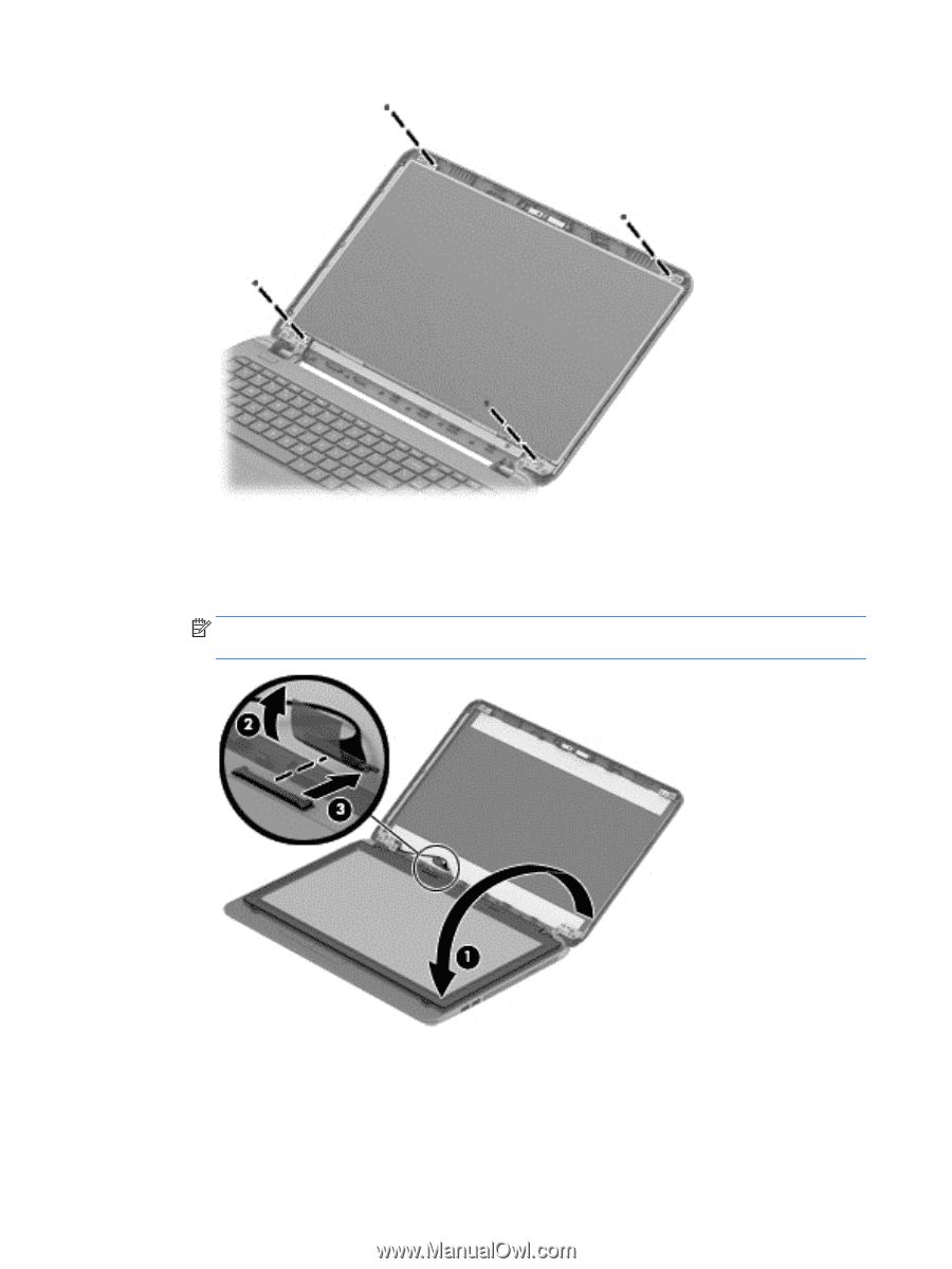
b.
Rotate the display panel onto the keyboard to gain access to the display cable connection on the
back of the panel
(1)
.
c.
On the back of the display panel, release the adhesive strip
(2)
that secures the display panel cable
to the display panel, and then disconnect the cable
(3)
.
NOTE:
In this procedure, the display will NOT be connected to the computer, as shown in the
following image.
4.
To remove the display hinges:
a.
Remove the eight Phillips PM2.5×3.5 screws
(1)
that secure the display hinges to
the display panel.
74
Chapter 6
Removal and replacement procedures for Authorized Service Provider parts