HP 15-g048ca HP 15 Notebook PC Compaq 15 Notebook PC Maintenance and Service G - Page 74
Display assembly
 |
View all HP 15-g048ca manuals
Add to My Manuals
Save this manual to your list of manuals |
Page 74 highlights
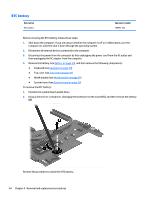
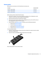
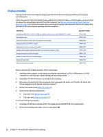
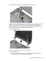
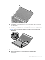
Display assembly This section describes removing the display assembly in its entirety and disassembling all the display subcomponents. If you only need to remove the display bezel, webcam/microphone module, or display panel, you do not need to remove the entire display assembly from the computer. See Display subcomponents (bezel, webcam, panel) on page 34 for more information about removing the display subcomponents that do not require that you remove the entire display assembly from the computer. Description Display assembly (39.6-cm [15.6-in] HD, anti-glare, touchscreen, for use in black HP 15 models Raw display panel Antennas (includes wireless antenna cables and transceivers) Display bezel for use in HP 15 models Display bezel for use in Compaq 15 models Display cable (includes display panel cable and webcam/microphone cable) Display enclosure for use in HP models Display enclosure for use in Compaq models Hinges (left and right) Webcam/microphone module Spare part number 747121-001 750635-001 749638-001 749644-001 749645-001 749646-001 749641-001 749642-001 749655-001 749654-001 Before removing the display assembly, follow these steps: 1. Shut down the computer. If you are unsure whether the computer is off or in Hibernation, turn the computer on, and then shut it down through the operating system. 2. Disconnect all external devices connected to the computer. 3. Disconnect the power from the computer by first unplugging the power cord from the AC outlet and then unplugging the AC adapter from the computer. 4. Remove the battery (see Battery on page 33). 5. Remove the following components: ● Keyboard (see Keyboard on page 39) ● Top cover (see Top cover on page 42) To remove the display assembly: 1. Disengage the adhesive and disconnect the display panel cable (1) from the system board. 2. Remove the display panel cable from its routing path (2). 66 Chapter 4 Removal and replacement procedures
-
 1
1 -
2
-
3
-
4
-
5
-
6
-
7
-
8
-
9
-
10
-
11
-
12
-
13
-
14
-
15
-
16
-
17
-
18
-
19
-
20
-
21
-
22
-
23
-
24
-
25
-
26
-
27
-
28
-
29
-
30
-
31
-
32
-
33
-
34
-
35
-
36
-
37
-
38
-
39
-
40
-
41
-
42
-
43
-
44
-
45
-
46
-
47
-
48
-
49
-
50
-
51
-
52
-
53
-
54
-
55
-
56
-
57
-
58
-
59
-
60
-
61
-
62
-
63
-
64
-
65
-
66
-
67
-
68
-
 69
69 -
 70
70 -
 71
71 -
 72
72 -
 73
73 -
 74
74 -
 75
75 -
 76
76 -
 77
77 -
 78
78 -
 79
79 -
80
-
81
-
82
-
83
-
84
-
85
-
86
-
87
-
88
-
89
-
90
-
91
-
92
-
93
-
94
-
95
-
96
-
97
-
98
-
99
-
100
-
101
-
102
-
103
-
104
-
105
-
106
-
107
-
108
-
109
-
110
-
111
-
112
-
113
-
114
-
115
-
116
-
117
-
118
-
119
-
120
-
121
-
122
 |
 |