HP 15-r052nr HP 15 Notebook PC HP 15 TouchSmart Notebook PC Compaq 15 Notebook - Page 73
When replacing the system board, be sure that the following components are removed from
 |
View all HP 15-r052nr manuals
Add to My Manuals
Save this manual to your list of manuals |
Page 73 highlights
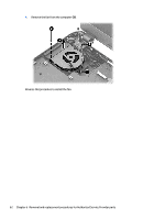
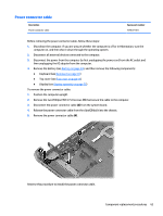
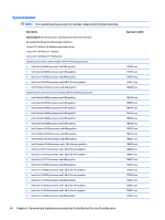
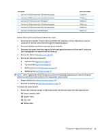
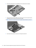
Description ● Intel Core i3-4030U processor and 1 GB of discrete graphics ● Intel Core i3-4030U processor and 2 GB of discrete graphics ● Intel Core i5-4210U processor and UMA graphics ● Intel Core i5-4210U processor and 1 GB of discrete graphics ● Intel Core i5-4210U processor and 2 GB of discrete graphics ● Intel Core i7-4510U processor and UMA graphics Spare part number 779468-xxx 779469-xxx 760968-xxx 788291-xxx 760970-xxx 784567-xxx Before removing the system board, follow these steps: 1. Shut down the computer. If you are unsure whether the computer is off or in Hibernation, turn the computer on, and then shut it down through the operating system. 2. Disconnect all external devices connected to the computer. 3. Disconnect the power from the computer by first unplugging the power cord from the AC outlet and then unplugging the AC adapter from the computer. 4. Remove the battery (see Battery on page 39). 5. Remove the following components: ● Keyboard (see Keyboard on page 43) ● Top cover (see Top cover on page 51) ● WLAN module (see WLAN module on page 59) ● Hard drive (see Hard drive on page 57) NOTE: When replacing the system board, be sure that the following components are removed from the defective system board and installed on the replacement system board: ● Memory module (see Memory module on page 74) ● Heat sink assembly (see Heat sink assembly on page 70) To remove the system board: 1. Position the computer upright, and then disconnect the following cables from the system board: (1): Power connector cable (2): Speaker cable (3): Fan cable (4): Display cable Component replacement procedures 65
-
 1
1 -
2
-
3
-
4
-
5
-
6
-
7
-
8
-
9
-
10
-
11
-
12
-
13
-
14
-
15
-
16
-
17
-
18
-
19
-
20
-
21
-
22
-
23
-
24
-
25
-
26
-
27
-
28
-
29
-
30
-
31
-
32
-
33
-
34
-
35
-
36
-
37
-
38
-
39
-
40
-
41
-
42
-
43
-
44
-
45
-
46
-
47
-
48
-
49
-
50
-
51
-
52
-
53
-
54
-
55
-
56
-
57
-
58
-
59
-
60
-
61
-
62
-
63
-
64
-
65
-
66
-
67
-
 68
68 -
 69
69 -
 70
70 -
 71
71 -
 72
72 -
 73
73 -
 74
74 -
 75
75 -
 76
76 -
 77
77 -
 78
78 -
79
-
80
-
81
-
82
-
83
-
84
-
85
-
86
-
87
-
88
-
89
-
90
-
91
-
92
-
93
-
94
-
95
-
96
-
97
-
98
-
99
-
100
-
101
-
102
-
103
-
104
-
105
-
106
-
107
-
108
-
109
-
110
-
111
-
112
-
113
-
114
-
115
-
116
-
117
-
118
-
119
-
120
-
121
-
122
 |
 |