HP 245 HP 450 Notebook PC and HP 455 Notebook PC Maintenance and Service Guide - Page 86
Support the display assembly when removing the following screws. Failure
 |
View all HP 245 manuals
Add to My Manuals
Save this manual to your list of manuals |
Page 86 highlights
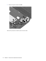
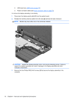
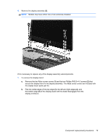
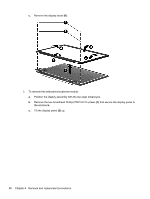
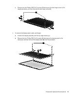
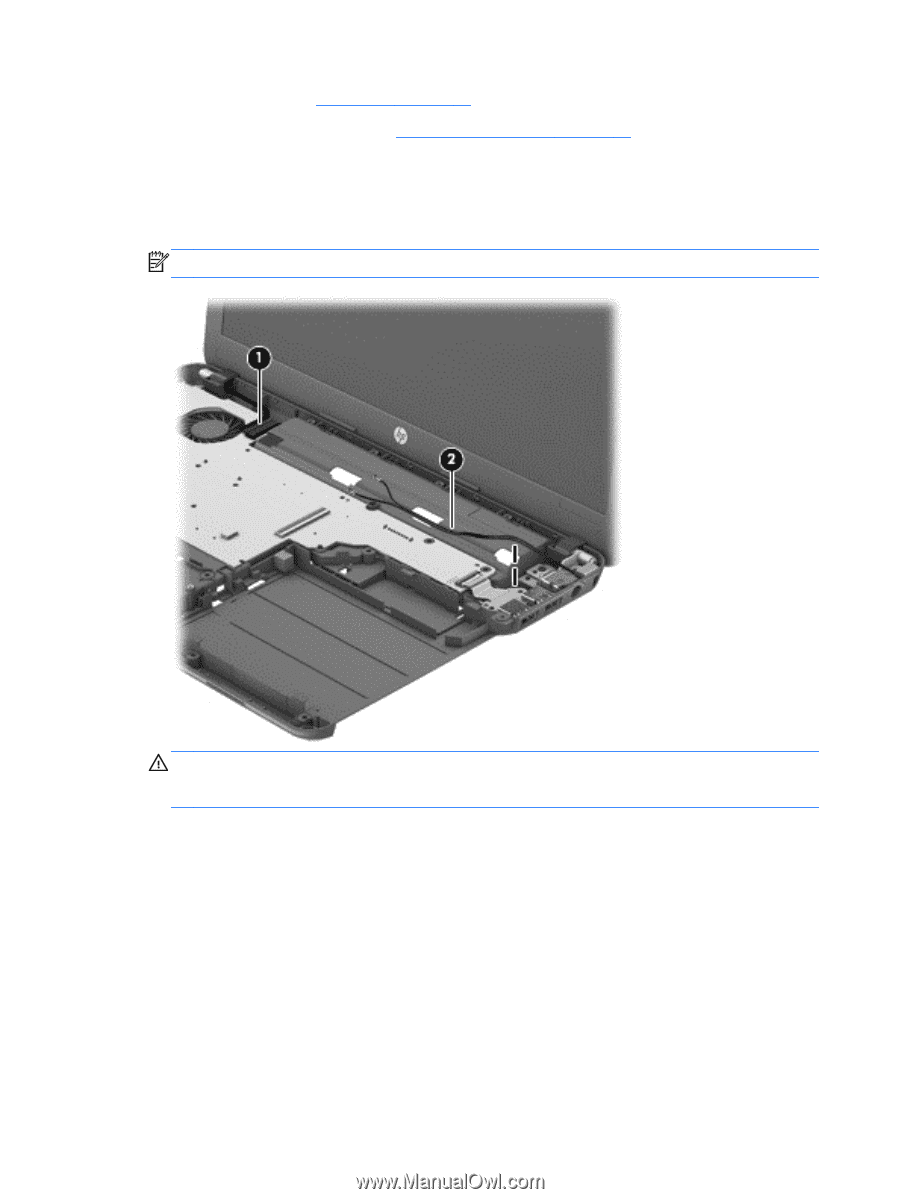
● USB board (see USB board on page 73) ● Power connector cable (see Power connector cable on page 75) To remove the display assembly in its entirety: 1. Disconnect the display panel cable (1) from the system board. 2. Release the wireless antenna cables from the clips (2) built into the base enclosure. NOTE: Models may have either one or two antennas installed. CAUTION: Support the display assembly when removing the following screws. Failure to support the display assembly can result in damage to the display assembly and other computer components. 3. Remove the five Phillips PM2.5×6.0 screws (1) that secure the display assembly to the computer. 78 Chapter 4 Removal and replacement procedures
-
 1
1 -
2
-
3
-
4
-
5
-
6
-
7
-
8
-
9
-
10
-
11
-
12
-
13
-
14
-
15
-
16
-
17
-
18
-
19
-
20
-
21
-
22
-
23
-
24
-
25
-
26
-
27
-
28
-
29
-
30
-
31
-
32
-
33
-
34
-
35
-
36
-
37
-
38
-
39
-
40
-
41
-
42
-
43
-
44
-
45
-
46
-
47
-
48
-
49
-
50
-
51
-
52
-
53
-
54
-
55
-
56
-
57
-
58
-
59
-
60
-
61
-
62
-
63
-
64
-
65
-
66
-
67
-
68
-
69
-
70
-
71
-
72
-
73
-
74
-
75
-
76
-
77
-
78
-
79
-
80
-
 81
81 -
 82
82 -
 83
83 -
 84
84 -
 85
85 -
 86
86 -
 87
87 -
 88
88 -
 89
89 -
 90
90 -
 91
91 -
92
-
93
-
94
-
95
-
96
-
97
-
98
-
99
-
100
-
101
-
102
-
103
-
104
-
105
-
106
-
107
-
108
-
109
-
110
-
111
-
112
-
113
-
114
-
115
-
116
-
117
-
118
-
119
-
120
-
121
-
122
-
123
-
124
-
125
-
126
-
127
-
128
-
129
-
130
-
131
-
132
-
133
-
134
-
135
-
136
-
137
-
138
-
139
-
140
-
141
-
142
 |
 |
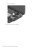
●
USB board (see
USB board
on page
73
)
●
Power connector cable (see
Power connector cable
on page
75
)
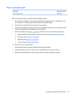
To remove the display assembly in its entirety:
1.
Disconnect the display panel cable
(1)
from the system board.
2.
Release the wireless antenna cables from the clips
(2)
built into the base enclosure.
NOTE:
Models may have either one or two antennas installed.
CAUTION:
Support the display assembly when removing the following screws. Failure to
support the display assembly can result in damage to the display assembly and other
computer components.
3.
Remove the five Phillips PM2.5×6.0 screws
(1)
that secure the display assembly to the
computer.
78
Chapter 4
Removal and replacement procedures