HP 353803-B22 HP StorageWorks 1500 Modular Smart Array installation and config - Page 2
Installation and configuration, overview, MSA1500 features, best practices, Cabling examples
 |
UPC - 808736781619
View all HP 353803-B22 manuals
Add to My Manuals
Save this manual to your list of manuals |
Page 2 highlights
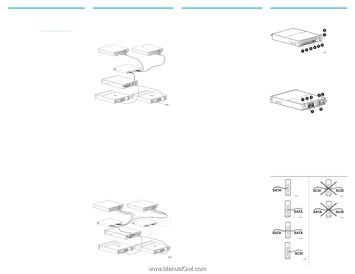
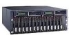
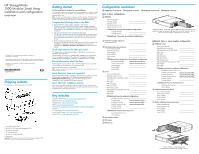
Installation and configuration best practices ● Use the configuration planning worksheet on the opposite side of this poster to help you gather all of the items required for installing your MSA array. ● Go to the MSA1500 website (http://www.hp.com/go/msa1500cs) to confirm your plans and review current information about the MSA1500. ● Install your MSA array in the sequence listed in this poster and in the installation guide. Several installation and configuration steps include dependencies; if you deviate from the listed sequence, you may have to uninstall and then reinstall your MSA. ● Use the installation guide to install and configure your MSA array. Details not provided in this overview are available in the guide. ● When planning your storage arrays and LUNs: - Customize the RAID level and striping method to the type of data that will be stored on the array. - Set the drive rebuild priority of the array to "high" to minimize exposure during a drive failure. - Optimize performance and redundancy by striping the drives in the array across separate storage enclosures on different SCSI buses, especially in mirrored environments using RAID 1 or RAID 1+0. Note: Depending on the number of drives that you include in an array, the ACU automatically assumes a default RAID type of RAID 6 (ADG), which maximizes fault tolerance and storage efficiency at a significant cost of I/O performance. For comparable fault tolerance but higher performance, consider using RAID 1+0. ● If your environment includes multiple servers, consider designating one of the servers as a management server to centralize your management tasks. It is from this server that you will perform SAN management tasks. ● Before installing your MSA array, consider redundancies of power, storage, and data paths. To provide redundant power, be sure to plug the two power supplies of the MSA array into separate Uninterruptable Power Supplies (UPS) on separate power sources. If you have only one UPS, maintain separate power paths by plugging one MSA power supply to the UPS on one power source, and plug the other MSA power supply to a separate power source. To provide redundant storage, configure your LUNs using fault-tolerant RAID levels and striping methods. To provide redundant data paths, you must include two isolated Fibre Channel fabrics and the associated hardware and software components in the configuration. (For example, you must include two MSA controllers, two interconnect devices, and two HBAs in each server.) ● When installing or updating HBA drivers, always use drivers and installation scripts provided on the MSA Support Software CD or the MSA website. Your MSA will not operate as intended if you update your HBA driver manually or use drivers obtained from the HBA manufacturer. ● After configuring the storage, remember to: - Identify the operating system (set the host mode profile) of each HBA with access to the storage. - Verify that each HBA in each server has been granted access to the storage. - Control access to the storage by indicating which HBA can access which array. ● If you are installing your MSA in a multipath environment that uses Secure Path, be sure to follow every server reboot prompt that is presented. Failure to acknowledge a server reboot prompt may result in your path redundancy not functioning properly. Be sure to reboot your server after the copy from the source media to the server is completed, and again after the redundancy driver is attached to the arrays. Cabling examples Singlepath cabling In singlepath configurations, one Fibre Channel cable connects a server HBA to a Fibre Channel network switch, and another Fibre Channel cable connects the switch to the MSA Fibre Channel I/O module (associated with the MSA controller in slot 1.) SCSI cables connect the external hard drive storage enclosures to the MSA SCSI I/O module. In the following illustration, two servers are accessing an MSA storage system. Example singlepath cabling diagram, showing two servers accessing a single-controller MSA1500 (with two attached MSA20 SATA storage enclosures) Multipath cabling In multipath configurations, the Fibre Channel cables connecting the servers, the switches, and the MSA must follow specific cabling rules. These rules ensure expected connectivity, performance, and path failover. These rules also aid the troubleshooting of future support issues. Multipathing cabling rules include: ● For the primary path from each server to the MSA - the HBA that boots up first must connect to a switch that connects to the MSA Fibre Channel I/O module associated with the MSA controller in slot 1. ● For the additional path from each server to the MSA - the HBA that boots up second must connect to a switch that connects to the MSA Fibre Channel I/O module associated with the MSA controller in slot 2. ● For the connections to the switch - designate the same port number on each switch to be for the two connections to one of the servers. Also designate the same port number on each switch to be for the connection to the MSA. The following illustration demonstrates multipathing cabling rules. The darker Fibre Channel cables represent the primary path to the MSA, and the lighter Fibre Channel cables represent the additional path to the MSA. Note the use of designated switch ports for the connections to the servers and the MSA. Installation and configuration overview The following sections in the installation guide detail the installation and configuration process. This overview is intended to help you plan for and obtain a basic understanding of this process and may be used as a master checklist. Be sure to use the installation guide to actually install your MSA. The installation guide is available on the Documentation CD and MSA website. Step 1: Review and confirm your plans HP recommends thoroughly researching, studying, and establishing an installation and configuration plan for your environment. Complete the Configuration worksheet on the opposite side of this poster, and go to the MSA website for current support and compatibility information. Record your plans for configuring the hard drives into logical units, and be sure to review all provided installation and configuration best practices. Step 2: Prepare your site Select a location that meets the environmental standards detailed in the installation guide. Approved environments include all of the following: adequate structural support, physical space, ventilation, temperature control, and sources of power. Step 3: Install MSA option kits If your plans include adding any of the available option kits to the MSA chassis, install them now. It is easier to install these options before racking the MSA. Some of the available option kits include an additional controller, additional Fibre Channel I/O module, and additional SCSI I/O modules. Step 4: Rack the MSA and the storage enclosures The MSA array and its supported external hard drive storage enclosures can be installed in most standard server racks. After installing the storage enclosures in the rack, you can install the hard drives into the enclosures. Step 5: Install the hard drives Now that the MSA and the storage enclosures are secured in the rack, you may install hard drives in the hard drive bays. Step 6: Prepare your servers Depending on your plans, you will connect your MSA array to a new or an existing server. In both scenarios, it is important that the server is operating properly before adding any MSA-specific components to it. If more than one server will access the MSA array, HP recommends designating one of the servers as a management server. It is from this server that you will perform your SAN management tasks. Step 7: Install the HBA in your servers The MSA can be deployed in a variety of operating system environments and configurations (including singlepath and multipath). Specific Host Bus Adapters (HBAs) are required for the different deployments. Obtain the correct HBA for your environment, and install it in the servers that will access the MSA. Step 8: Prepare your switches In an existing SAN, the switches and hubs are already set up and configured, but if you are deploying your MSA in a new SAN, install and configure your Fibre Channel interconnect devices now. Step 9: Connect the cables After preparing the SAN and installing the MSA array, the storage enclosures, and the hard drives, connect all of the cables between the devices. This includes SCSI cables, Fibre Channel cables, and power cords. Note: Multipath configurations have exacting cable-connection requirements. See the Cabling examples section of this document and refer to the installation guide. Step 10: Power on the devices After the MSA is installed and connected to the SAN, power on all of the devices in the SAN. Note: Be sure to follow the power-on sequence as detailed in the installation guide. Step 11: Configure your MSA After the servers and Fibre Channel interconnect devices are set up and the MSA array is physically installed, connected, and powered on, configure the MSA controller and the storage. Note: Be sure to follow the configuration procedures for your operating system as detailed in the installation guide. MSA1500 features When unpacking your MSA array, take the time to identify its primary features. Front features 1 Blank for an additional controller (in controller slot 2) 2 Serial port for a connection to the Command Line Interface (CLI) 3 MSA controller (in controller slot 1) 4 Controller status lights 5 Controller LCD display panel 6 Controller LCD display panel push buttons 7 Chassis Power On/Standby button 8 Chassis status lights Rear features 15936 1 Fibre Channel I/O module (for the controller in controller slot 1) 2 Chassis slot diagram 3 Fan modules 4 SCSI I/O module 5 Power supply modules 6 Blank for additional Fibre Channel I/O module (for the controller in controller slot 2) 7 Blanks for additional SCSI I/O modules SCSI module features Each MSA1500 SCSI I/O module has two ports. Depending on the type of external hard drive storage enclosure you plan to connect, one or both of the ports may be used. ● When connecting SATA enclsoures, both ports may be used. ● When connecting SCSI enclosures, only the right port may be used. The following table illustrates supported and unsupported cable connections to the MSA SCSI I/O module. Supported SCSI cable connections Unsupported SCSI cable connections Example multipath cabling diagram, showing two servers accessing a dual-controller MSA1500 (with two attached MSA20 SATA storage enclosures)
-
 1
1 -
 2
2
 |
 |