HP 455071-L21 L2105tm / 2209t LCD Touch Monitors - User Guide - Page 21
Appendix, Connector pin assignment
 |
View all HP 455071-L21 manuals
Add to My Manuals
Save this manual to your list of manuals |
Page 21 highlights
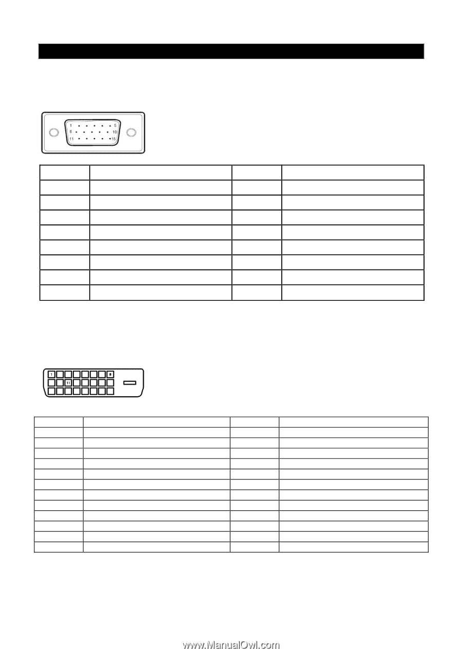
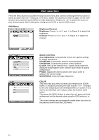
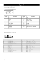
Connector pin assignment • 15 pin color display signal cable: Appendix PIN No. 1. 2. 3. 4. 5. 6. 7. 8. Description Red Green Blue Monitor ground DDC-return R-ground G-ground B-ground 24 pin DVD-D display signal cable: PIN No. 9. 10. 11. 12. 13. 14. 15. Description +5V Logic ground Monitor ground DDC-serial data H-sync V-sync DDC-serial time sequence Pin No. 1 2 3 4 5 6 7 8 9 10 11 12 Description TMDS Data 2 TMDS Data 2 + TMDS Data 2 / 4 Shield TMDS Data 4 TMDS Data 4 + DDC Clock DDC Data No Connect TMDS Data 1 TMDS Data 1 + TMDS Data 1 / 3 Shield TMDS Data 3 - Pin No. 13 14 15 16 17 18 19 20 21 22 23 24 Description TMDS Data 3 + +3.3/+5V Power (from PC) Ground (Return for +5V) Hot Plug Detect TMDS Data 0 TMDS Data 0 + TMDS Data 0 / 5 Shield TMDS Data 5 TMDS Data 5 + TMDS Clock Shield TMDS Clock + TMDS Clock - 16
-
 1
1 -
2
-
3
-
4
-
5
-
6
-
7
-
8
-
9
-
10
-
11
-
12
-
13
-
14
-
15
-
 16
16 -
 17
17 -
 18
18 -
 19
19 -
 20
20 -
 21
21
 |
 |