HP 489183-B21 HP 4X DDR IB Switch Module Installation Instructions for the HP - Page 1
HP 489183-B21 - InfiniBand DDR Switch Manual
 |
UPC - 884420049678
View all HP 489183-B21 manuals
Add to My Manuals
Save this manual to your list of manuals |
Page 1 highlights
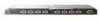
HP 4X DDR IB Switch Module Installation Instructions for the HP c-Class BladeSystem © Copyright 2006 Hewlett-Packard Development Company, L.P. The information contained herein is subject to change without notice. The only warranties for HP products and services are set forth in the express warranty statements accompanying such products and services. Nothing herein should be construed as constituting an additional warranty. HP shall not be liable for technical or editorial errors or omissions contained herein. July 2006 (First Edition) Part Number 433375-001 Printed in the US Printed in the US Overview This card provides instructions for installing an HP 4X DDR IB Switch Module in a c-Class enclosure. Kit contents The kit contents include the following items: • An HP 4X DDR IB Switch Module for the HP c-Class BladeSystem • This installation card • Warranty documentation HP 4X DDR IB switch module Additional information Mezzanine card installation determines bay assignments for interconnect module installation. For more information on the association between the mezzanine connector and the interconnect bays, see the HP BladeSystem enclosure setup and installation guide or HP BladeSystem enclosure installation poster. For specific port connections for each blade, see the HP BladeSystem Onboard Administrator User Guide. Connections differ by blade type. The information in this guide explains cabling between the HP 4X DDR IB switch module and the network switches. The Onboard Administrator screen example is a reference for port mapping. LEDs HP Confidential Connectors NOTE: See the HP BladeSystem enclosure setup and installation guide for more information on the BladeSystem port mapping. Item Description 1 External IB ports (1-8) 2 Debug port Item Description Status 1 Unit ID LED Blue = Activated Off = Deactivated 2 Internal health Green = Normal LED Amber = Component degraded Off = Power off 3 Logical Amber = Logical link established link/activity LED Amber flashing = Logical link with activity* Off = No logical link established 4 Physical link LED Green = Physical link established Green flashing = Physical link error Off = No physical link established *The logical link-activity LED flashes with greater frequency as network activity increases. Installing the module 1. Prepare the bay: a. Remove any devices or blanks. b. Remove the divider.
-
 1
1 -
 2
2
 |
 |
