HP 6120G/XG HP ProCurve 6120G/XG Blade Switch Installation Instructions - Page 2
Firmware requirements, Front Panel - blade switch firmware
 |
View all HP 6120G/XG manuals
Add to My Manuals
Save this manual to your list of manuals |
Page 2 highlights
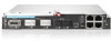
switch CLI, accessing it via serial interface attached to OA and/or USB interface attached to the blade. When using optional transceiver modules or direct-attach cables, order the modules and cables separately. For more information, see the QuickSpecs on the HP website (http://www.hp.com/go/bladesystem/interconnects). For more information on BladeSystem port mapping, see the HP BladeSystem enclosure setup and installation guide that shipped with the enclosure. For the most current product information, see the release notes at http://www.hp.com/go/bladesystem/documentation Firmware requirements Always install the most current firmware or software for the following items: Server blade system ROMs Ethernet mezzanines HP BladeSystem Onboard Administrator HP ProCurve blade switch For additional information on required firmware or software versions and to download firmware or software updates, see the HP website: 1. Go to http://www.hp.com/#Support. 2. Click the "Download drivers and software" radio button. 3. Enter "6120G/XG" in the text box and click "Go". 4. Click the link for your operating system. 5. Download the appropriate software or firmware. Front Panel Item Description 1 Port C1 (10GBASE-CX4) 2 Port X1 XFP (10-GbE) slot* 3 Port X2 XFP (10-GbE) slot* 4 Port S1 SFP (1-GbE) slot** 5 Port S2 SFP (1-GbE) slot** 6 Console port (USB 2.0 mini-AB connector) 7 Clear button 8 Ports 1-4 (10/100/1000BASE-T) 9 Reset button (recessed) * Supports 10GBASE-SR XFP and 10GBASE-LR XFP pluggable optical transceiver modules ** Supports 1000BASE-T SFP, 1000BASE-SX SFP, and 1000BASELX SFP pluggable optical transceiver modules LEDs Item LED description 1 Module locator (UID) Status Blue = Module ID selected Off = Module ID not selected 2 Module status (health) Green = Normal operation Amber = Fault Off = Power off 3 C1 port status Green = Port is connected to the (10GBASE-CX4) network. Amber = Fault Off = Not connected 4 C1 activity Green flashing = Activity 5 Port X1/X2 status Green = Port is connected to the (XFP connector) network. Amber = Fault Off = Not connected 6 Port X1/X2 activity Green flashing = Activity 7 Port S1/S2 status Green = Port is connected to the (SFP connector) network. Amber = Fault Off = Not connected 8 Port S1/S2 activity Green flashing = Activity 9 Port 1-4 port status Green = Port is connected to the network. Amber = Fault Off = Not connected 10 Port 1-4 link/activity Green flashing = 10/100 activity 11 Port 1-4 link/activity Amber flashing = 1000 activity
-
 1
1 -
 2
2 -
 3
3 -
 4
4
 |
 |
