HP 6120G/XG HP ProCurve 6120XG Blade Switch Installation Instructions - Page 2
Firmware requirements, Front Panel - blade switch firmware
 |
View all HP 6120G/XG manuals
Add to My Manuals
Save this manual to your list of manuals |
Page 2 highlights
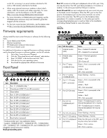
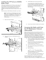
switch CLI, accessing it via serial interface attached to OA and/or USB interface attached to the blade. When using optional transceiver modules or direct attach cables, order the modules and cables separately. For more information, see the QuickSpecs on the HP website (http://www.hp.com/go/bladesystem/interconnects). For more information on BladeSystem port mapping, see the HP BladeSystem enclosure setup and installation guide that shipped with the enclosure. For the most current product information, see the release notes at http://www.hp.com/go/bladesystem/documentation. Firmware requirements Always install the most current firmware or software for the following items: Server blade system ROMs Ethernet mezzanines HP BladeSystem Onboard Administrator HP ProCurve blade switch For additional information on required firmware or software versions and to download firmware or software updates, see the HP website: 1. Go to http://www.hp.com/#Support. 2. Click the "Download drivers and software" radio button. 3. Enter "6120XG" in the text box and click "Go". 4. Click the link for your operating system. 5. Download the appropriate software or firmware. Front Panel Item Description 1 Port 17 (10GBASE-CX4) * 2 Console port (USB 2.0 mini-AB connector) 3 Clear button 4 Port 17 SFP+ (10-GbE) slot * † 5 Port 18 SFP+ (10-GbE) slot † 6 Port 19 SFP+ (10-GbE) slot † 7 Port 20 SFP+ (10-GbE) slot † 8 Port 21 SFP+ (10-GbE) slot † 9 Port 22 SFP+ (10-GbE) slot † 10 Port 23 SFP+ (10-GbE) slot * † 11 Port 24 SFP+ (10-GbE) slot * † 12 Reset button (recessed) * Dual-personality port. See explanation below. † Supports 10GBASE-SR SFP+, 10GBASE-LR SFP+, 10GBASE-LRM SFP+, 1000BASE-T SFP, 1000BASE-SX SFP, and 1000BASE-LX SFP pluggable optical transceiver modules. Dual-personality ports Port 17 consists of a CX4 port multiplexed with an SFP+ port. Only one may be active. The SFP+ port takes precedence: if it contains a module, it is the active port and the CX4 port is inactive. Ports 23 and 24 are each multiplexed with inter-switch link ports on the blade switch's backplane. Either the SFP+ port on the front panel or the backplane port can be active, but both can not be active at the same time. The SFP+ port on the frontplane takes precedence: if it contains a module, it is the active port and its corresponding backplane port is inactive. Refer to the Installation and Getting Started Guide for more information. LEDs Item LED description 1 Module locator (UID) Status Blue = Module ID selected Off = Module ID not selected 2 Module status (health) Green = Normal operation Amber = Fault Off = Power off 3 Port 17 status (10GBASE-CX4) Green = Port is connected to the network. Amber = Fault Off = Not connected 4 Port 17 activity (10GBASE-CX4) Green flashing = Activity 5 Port 17-22 status (SFP+ connector) Green = Port is connected to the network. Amber = Fault Off = Not connected 6 Port 23-24 status Green = Port is connected to the network. Amber = Fault Off = Not connected 7 Port 23-24 multiplexed port status Green = Frontplane port is active. Internal (backplane) link is inactive. Off = Frontplane port is inactive. Internal (backplane) link may be active. 8 Port 23-24 activity Green flashing = Activity 9 Port 17-22 activity Green flashing = Activity 10 Port 17 multiplexed Either the CX4 port or the SFP+ port port status may be active, but not both. Green = Port is active. Off = Port is inactive.
-
 1
1 -
 2
2 -
 3
3 -
 4
4
 |
 |