HP 9000 rp7410 Generic Site Preparation Guide - Edition 6 - Page 19
Computer Room Preparation, Airflow, Row Orientation
 |
View all HP 9000 rp7410 manuals
Add to My Manuals
Save this manual to your list of manuals |
Page 19 highlights
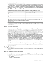
• Computer room preparation • Airflow • Cooling requirements • Humidity level • ESD prevention • Acoustics Computer Room Preparation Consider the following guidelines to prepare a computer room for a product: • Locate the computer room away from the exterior walls of the building to avoid the heat gain from windows and exterior wall surfaces. • When exterior windows are unavoidable, use windows that are double- or triple-glazed and shaded to prevent direct sunlight from entering the computer room. For more information, see the section titled "Windows" (page 27). • Maintain the computer room at a positive pressure relative to surrounding spaces. • Use a vapor barrier installed around the entire computer room envelope to restrain moisture migration. • Caulk and vapor seal all pipes and cables that penetrate the envelope. • Use a raised floor system at least 18 inches (45.72 cm) high for the minimum favorable room air distribution to ensure good static air pressure beneath the flooring (under floor distribution). • Ensure a minimum clearance of 12 inches (30.48 cm) between the top of the product cabinet and the ceiling to allow for return airflow and to ensure that all ceiling tiles are in place, except where fire sprinkler heads call for greater clearance. • Allow 18 inches (45.72 cm) (or local code minimum clearance) from the top of any device (product cabinet, cable trays) to the fire sprinkler heads. Airflow Ensure that separate hot and cold aisles are parallel to airflow patterns. • This recommendation causes cooling air to be released into cold aisles, where opposing rows have intake grills oriented. • Ensure that opposing row exhaust grills face each other, without cooling air. • A parallel orientation encourages low impedance airflow back to the HVAC. • Route cables underneath the floor to be parallel to the airflow to prevent airdams, if raised flooring is used. • Keep air throws from HVAC equipment to the heat loads they serve within 75 feet (22.86 m) of each other. Row Orientation Row orientation has an impact on the airflow, temperature, particulate contamination, and power distribution of the environment. Consider the following when planning equipment layout: • Use hot aisle (exhaust) and cold aisle (intake) orientation. • Route the airflow (air conditioned supply and return) to be parallel to the aisleways. • Adhere to the temperature and humidity standards located at the following web address: http://standards.corp.hp.com/smc/hpstd/pdf/F-HP0000501.pdf HP product specifications for temperature and humidity are measured at 1.9 inches (5.0 cm) from air intake center of device. Environmental Elements 19
-
 1
1 -
2
-
3
-
4
-
5
-
6
-
7
-
8
-
9
-
10
-
11
-
12
-
13
-
 14
14 -
 15
15 -
 16
16 -
 17
17 -
 18
18 -
 19
19 -
 20
20 -
 21
21 -
 22
22 -
 23
23 -
 24
24 -
25
-
26
-
27
-
28
-
29
-
30
-
31
-
32
-
33
-
34
-
35
-
36
-
37
-
38
-
39
-
40
-
41
-
42
-
43
-
44
-
45
-
46
 |
 |