HP A4500A Basic Cable Connections - hp rp2400 Series of Servers - Page 12
rp24xx Server RS-232 System Local Console Installation, Console Configuration (VT100 mode) - emulator
 |
View all HP A4500A manuals
Add to My Manuals
Save this manual to your list of manuals |
Page 12 highlights
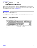
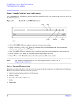
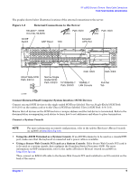
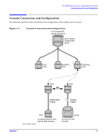
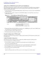
HP rp2400 Series of Servers - Basic Cable Connections Console Connection and Configuration rp24xx Server RS-232 System Local Console Installation The following describes how to install a system console on an rp24xx Server. The HP-700 series terminal is used as an example. Other terminals may be used as a system console as long as they are configured for VT100 terminal emulation mode. 1. Connect the 25-pin end of the A5191-63001 adapter cable to the 25-pin connector on the Console/UPS Port located on the rear. 2. Connect the 9-pin, "Console," connector of a A5191-63001 adapter to the 9-pin D-type connector on a 24542G RS-232 cable. Figure 1-5 Console/Remote-Modem/UPS Connector wi n urbo Path: 0/2/0 wi n urbo Path: 0/4/ 0 100-240V~, 600W 6.0-2.6A, 50-60Hz A B Ultra 2 W ide SCSI Path: 0/0/1/ 0 GSP Reset TO C Narro w S ingle Ended SCSI Path: 0/0/2/ 0 10/100BASE- T 10BASE- T Path: 0/0/0/ 0 LAN Consol e Console/ UPS Por t Path: 0/6/2 ccrr012 Console/Remote-Modem/UPS Connector (D-Type 25-Pin female) Requires: A5191-63001 "W" adapter cable Path: 0/6/ 0 3. Connect the 25-pin end of the 24542G serial cable to the serial/RS232 port on the Console. (RS232 Serial Port labeling may vary depending on manufacturer.) 4. Connect the System Console to input AC power. 5. Turn the System Console AC power switch to ON. Console Configuration (VT100 mode) The following describes the steps required to configure system consoles for VT-100 mode for operation with the rp24xx server. C1099A VT-100 Mode Configuration. The following procedure outlines the steps to configure the C1099A terminal for VT-100 operation. To access the Setup menu in HPTerm emulation: 1. Press the F10 key to display the terminal local function labels, then Press F8 (config keys). You are now in the Quick (F1) menu. 2. Select the VT100 emulation by using the space bar to navigate through the available options. 3. Press the ESC key to save selected setup parameters and to exit the Setup menu. 4. Press the Y key when the blinking prompt Save all? (Y/N) appears in the upper right corner of the menu to save the settings in non-volatile memory. 12 Chapter 1
-
 1
1 -
2
-
3
-
4
-
5
-
6
-
 7
7 -
 8
8 -
 9
9 -
 10
10 -
 11
11 -
 12
12 -
 13
13 -
 14
14
 |
 |
