HP A7533A Brocade Web Tools Administrator's Guide v6.2.0 (53-1001194-01, April - Page 297
CUP port connectivity configuration
 |
UPC - 829160830858
View all HP A7533A manuals
Add to My Manuals
Save this manual to your list of manuals |
Page 297 highlights
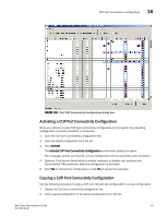
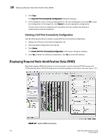
CUP port connectivity configuration 18 CUP port connectivity configuration In the Port Connectivity subpanel, you can manage the configuration files and active configuration. All CUP configuration files and the active configuration are listed in a table. The active configuration is listed as "Active Configuration*" and the description in the table is "Current active configuration on switch." The other special configuration file is the IPL. Any other files displayed are user-defined configurations and are stored on the switch. You can create, activate, copy, or delete saved CUP port connectivity configurations; however, you can only edit or copy a configuration while it is active.You can also activate, edit, or copy the IPL configuration. You must have FMS mode enabled before you can make any changes to the configurations. Click Refresh to get the latest configuration file list from the switch. When creating a new configuration or editing an existing configuration, keep in mind that Web Tools port name input is restricted to printable ASCII characters. Therefore, when Web Tools displays a port name, if there are characters beyond printable ASCII characters (which would have been created by the Host Program), those characters are displayed as dots (.). When initially installed, a switch allows any port to dynamically communicate with any other port. Two connectivity attributes are defined to restrict this any-to-any capability for external ports: Block and Prohibit. Block is a port connectivity attribute that prevents all communication through a port. Prohibit is the port connectivity attribute that prohibits or allows dynamic communication between ports when a port is not blocked. Each port has a vector specifying its Prohibit attribute with respect to each of the other ports in the switch. This attribute is always set symmetrically in that a pair of ports is either prohibited or allowed to communicate dynamically. The Port Connectivity table (shown in Figure 136 on page 271) displays the Port number (in physical-location format), Port Name (port address name), Block attribute, Prohibit attribute, and Area Id (port address, displayed in hexadecimal) in fixed columns. The right side is a port matrix, which lists all ports by Area ID and identifies prohibited ports. Those columns are scrollable and swappable. Viewing CUP Port Connectivity Configurations Use the following procedure to display a list of CUP port connectivity configurations. 1. Click a FICON-enabled switch from the Fabric Tree. 2. Open the Switch Administration window as described on page 41. 3. Click the FICON CUP tab. The FICON CUP page displays the FICON Management Server page in front (see Figure 134 on page 265). All attributes on this page are read-only until FMS mode is enabled. 4. Click the CUP Port Connectivity subtab. Creating or Editing CUP Port Connectivity Configurations Use the following procedure to create a new CUP port connectivity configuration or to edit an existing configuration. 1. Display the CUP port connectivity configuration list. 2. You can either create a new configuration or edit an existing configuration. Web Tools Administrator's Guide 269 53-1001194-01
-
 1
1 -
2
-
3
-
4
-
5
-
6
-
7
-
8
-
9
-
10
-
11
-
12
-
13
-
14
-
15
-
16
-
17
-
18
-
19
-
20
-
21
-
22
-
23
-
24
-
25
-
26
-
27
-
28
-
29
-
30
-
31
-
32
-
33
-
34
-
35
-
36
-
37
-
38
-
39
-
40
-
41
-
42
-
43
-
44
-
45
-
46
-
47
-
48
-
49
-
50
-
51
-
52
-
53
-
54
-
55
-
56
-
57
-
58
-
59
-
60
-
61
-
62
-
63
-
64
-
65
-
66
-
67
-
68
-
69
-
70
-
71
-
72
-
73
-
74
-
75
-
76
-
77
-
78
-
79
-
80
-
81
-
82
-
83
-
84
-
85
-
86
-
87
-
88
-
89
-
90
-
91
-
92
-
93
-
94
-
95
-
96
-
97
-
98
-
99
-
100
-
101
-
102
-
103
-
104
-
105
-
106
-
107
-
108
-
109
-
110
-
111
-
112
-
113
-
114
-
115
-
116
-
117
-
118
-
119
-
120
-
121
-
122
-
123
-
124
-
125
-
126
-
127
-
128
-
129
-
130
-
131
-
132
-
133
-
134
-
135
-
136
-
137
-
138
-
139
-
140
-
141
-
142
-
143
-
144
-
145
-
146
-
147
-
148
-
149
-
150
-
151
-
152
-
153
-
154
-
155
-
156
-
157
-
158
-
159
-
160
-
161
-
162
-
163
-
164
-
165
-
166
-
167
-
168
-
169
-
170
-
171
-
172
-
173
-
174
-
175
-
176
-
177
-
178
-
179
-
180
-
181
-
182
-
183
-
184
-
185
-
186
-
187
-
188
-
189
-
190
-
191
-
192
-
193
-
194
-
195
-
196
-
197
-
198
-
199
-
200
-
201
-
202
-
203
-
204
-
205
-
206
-
207
-
208
-
209
-
210
-
211
-
212
-
213
-
214
-
215
-
216
-
217
-
218
-
219
-
220
-
221
-
222
-
223
-
224
-
225
-
226
-
227
-
228
-
229
-
230
-
231
-
232
-
233
-
234
-
235
-
236
-
237
-
238
-
239
-
240
-
241
-
242
-
243
-
244
-
245
-
246
-
247
-
248
-
249
-
250
-
251
-
252
-
253
-
254
-
255
-
256
-
257
-
258
-
259
-
260
-
261
-
262
-
263
-
264
-
265
-
266
-
267
-
268
-
269
-
270
-
271
-
272
-
273
-
274
-
275
-
276
-
277
-
278
-
279
-
280
-
281
-
282
-
283
-
284
-
285
-
286
-
287
-
288
-
289
-
290
-
291
-
 292
292 -
 293
293 -
 294
294 -
 295
295 -
 296
296 -
 297
297 -
 298
298 -
 299
299 -
 300
300 -
 301
301 -
 302
302 -
303
-
304
-
305
-
306
-
307
-
308
-
309
-
310
-
311
-
312
-
313
-
314
 |
 |