HP AF611A HP 1X4 Server Console Switch User Guide - Page 9
Connecting peripherals, Connecting computers, Powering up the console switch - cables
 |
UPC - 882780907553
View all HP AF611A manuals
Add to My Manuals
Save this manual to your list of manuals |
Page 9 highlights
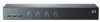
4. Secure the console switch to the rails of the rack using the approved method of the rack manufacturer. Connecting peripherals NOTE: HP recommends using only the HP 1X4 KVM Console 6-foot PS/2 cable (AF612A) and HP 1X4 KVM USB cable (AF613A) for connecting peripherals. Connect the shared PS/2 or USB keyboard, monitor and mouse, as well as other USB devices to the console switch. If connecting PS/2 computers, use the 3-in-1 keyboard, monitor and mouse cable. If connecting USB computers, use the USB cable and separate VGA cable Connecting computers Connect each computer to the console switch via the rear panel CPU ports labeled PC1 through PC4. Powering up the console switch 1. Connect to AC power. 2. Power up the connected computers, ensuring that the keyboard and mouse are enabled. The console switch features the following LED indicators: • Green (KVM): o Off-No device connected. o On (Constant)-Target device is connected but not selected. o On (Flashing)-Target device is connected and selected. • Yellow (Hub): o Off-No device connected. o On (Constant)-Target device is connected but not selected. o On (Slow flashing 1Hz)-Target device is connected and selected. o On (Fast flashing 10Hz)-Target device is disconnected and pending. Installing the console switch 9
-
 1
1 -
2
-
3
-
 4
4 -
 5
5 -
 6
6 -
 7
7 -
 8
8 -
 9
9 -
 10
10 -
 11
11 -
 12
12 -
 13
13 -
 14
14 -
15
-
16
-
17
-
18
-
19
-
20
-
21
 |
 |
