HP BL40p The Intel processor roadmap for industry-standard servers technology - Page 6
front end of the microprocessor; the execution engine; and the retire unit The front end
 |
UPC - 613326517680
View all HP BL40p manuals
Add to My Manuals
Save this manual to your list of manuals |
Page 6 highlights
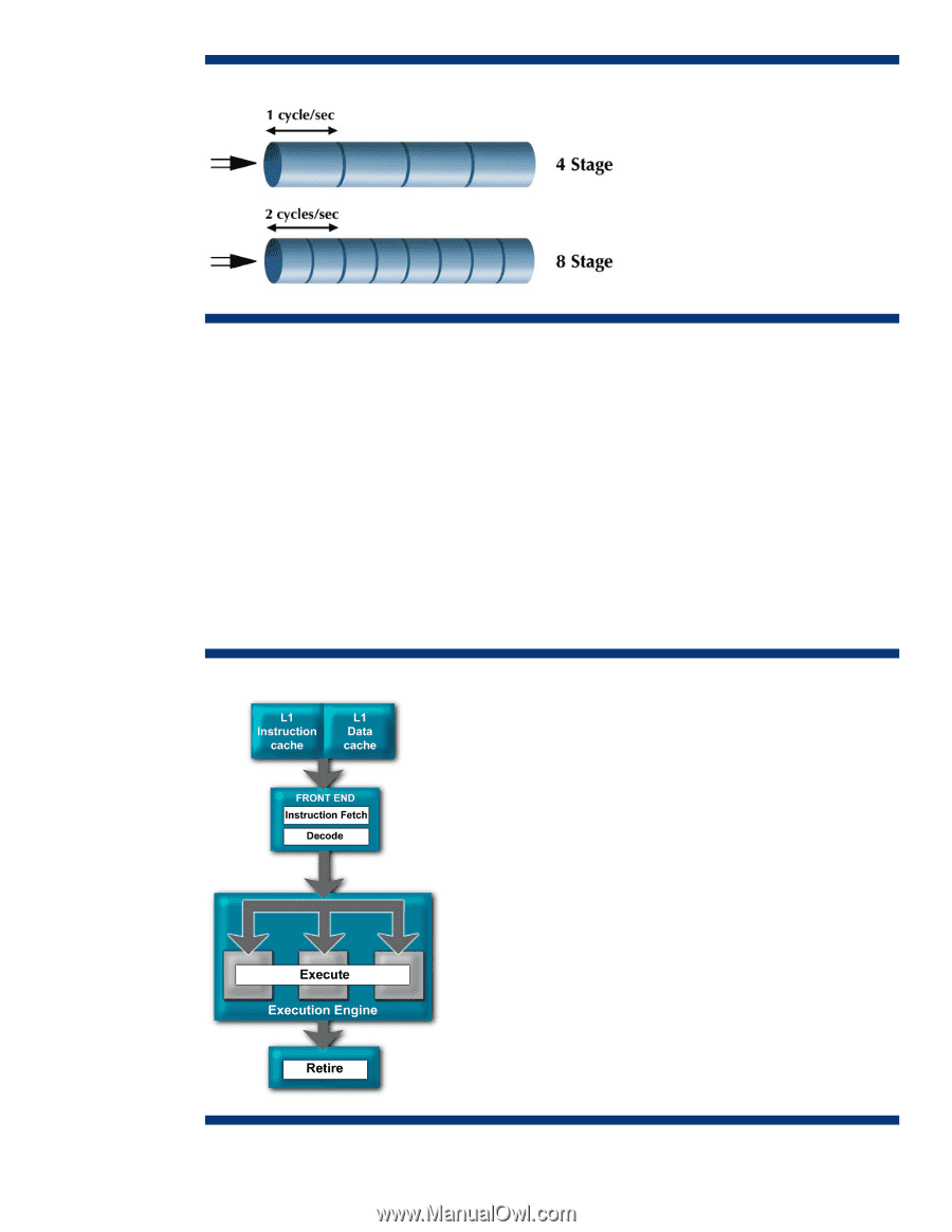
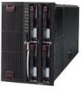
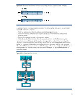
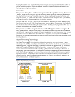
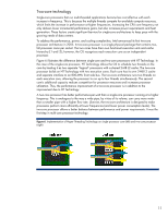
Figure 3. By decreasing the amount of work done in each stage, the clock frequency can be increased. A basic structure for a computer pipeline consists of the following four steps, which are performed repeatedly to execute a program. 1. Fetch the next instruction from the address stored in the program counter. 2. Store that instruction in the instruction register, decode it, and increment the address in the program counter. 3. Execute the instruction currently in the instruction register. 4. Write the results of that instruction from the execution unit back into the destination register. Typical processor architectures split the pipeline into segments that perform those basic steps: the "front end" of the microprocessor; the execution engine; and the retire unit (Figure 4). The front end fetches the instruction and decodes it into smaller instructions (commonly referred to as micro-ops). These decoded instructions are sent to one of the three types of execution units (integer, load/store, or floating point) to be executed. Finally, the instruction is retired and the result is written back to its destination register. Figure 4. Basic 4-stage pipeline schematic 6
-
 1
1 -
 2
2 -
 3
3 -
 4
4 -
 5
5 -
 6
6 -
 7
7 -
 8
8 -
 9
9 -
 10
10 -
 11
11 -
 12
12 -
13
-
14
-
15
-
16
-
17
-
18
-
19
-
20
-
21
-
22
 |
 |