HP BL465c HP ProLiant BL465c Generation 5 Server Blade User Guide - Page 16
Interconnect bay numbering and device mapping, Connecting to the network, Installing a server blade - drive blank
 |
UPC - 882780893504
View all HP BL465c manuals
Add to My Manuals
Save this manual to your list of manuals |
Page 16 highlights
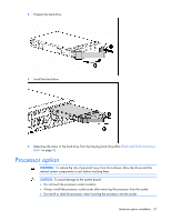
Interconnect bay numbering and device mapping To support network connections for specific signals, install an interconnect module in the bay corresponding to the embedded NIC or mezzanine signals. Server blade signal Interconnect bay NIC 1 (Embedded) 1 Interconnect bay labels NIC 2 (Embedded) Mezzanine 1 Mezzanine 2 2 3 and 4 5 and 6 7 and 8 For detailed port mapping information, see the HP BladeSystem enclosure installation poster or the HP BladeSystem enclosure setup and installation guide on the HP website (http://www.hp.com/go/bladesystem/documentation). Connecting to the network To connect the HP BladeSystem to a network, each enclosure must be configured with network interconnect devices to manage signals between the server blades and the external network. Two types of interconnect modules are available for HP BladeSystem c-Class enclosures: Pass-thru modules and switch modules. For more information about interconnect module options, see the HP website (http://www.hp.com/go/bladesystem/interconnects). Installing a server blade CAUTION: To prevent improper cooling and thermal damage, do not operate the server blade or the enclosure unless all hard drive and device bays are populated with either a component or a blank. Setup 16
-
 1
1 -
2
-
3
-
4
-
5
-
6
-
7
-
8
-
9
-
10
-
 11
11 -
 12
12 -
 13
13 -
 14
14 -
 15
15 -
 16
16 -
 17
17 -
 18
18 -
 19
19 -
 20
20 -
 21
21 -
22
-
23
-
24
-
25
-
26
-
27
-
28
-
29
-
30
-
31
-
32
-
33
-
34
-
35
-
36
-
37
-
38
-
39
-
40
-
41
-
42
-
43
-
44
-
45
-
46
-
47
-
48
-
49
-
50
-
51
-
52
-
53
-
54
-
55
-
56
-
57
-
58
-
59
-
60
-
61
-
62
-
63
-
64
-
65
-
66
-
67
-
68
-
69
-
70
-
71
-
72
-
73
-
74
-
75
-
76
-
77
-
78
-
79
-
80
-
81
-
82
-
83
-
84
-
85
-
86
-
87
-
88
-
89
-
90
-
91
-
92
 |
 |
