HP BL680c HP BladeSystem c-Class architecture - Page 9
Interconnect form factors, Star topology, interconnect modules.
 |
UPC - 884420396314
View all HP BL680c manuals
Add to My Manuals
Save this manual to your list of manuals |
Page 9 highlights
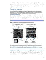
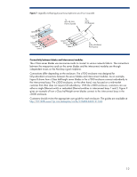
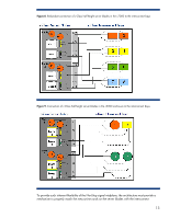
variety of memory technologies that give customers options when weighing memory capacity, power use, and cost. Interconnect form factors HP selected a single-wide/double-wide interconnect form factor to achieve efficient use of space and improved performance. A single interconnect bay can accommodate two smaller interconnect modules in a scale-out configuration or a larger, higher-bandwidth interconnect module for scale-up performance (Figure 5). This provides the same efficient use of space as the scale-up/scale-out device bays. Figure 5. Single-wide/double-wide interconnect form factor of c-Class enclosures Single-wide interconnect modules Double-wide interconnect modules Two midplane connectors on the same PCB Using scalable interconnect modules provides many of the same advantages as the scalable device bays: • Simpler connectivity and improved reliability when scaling from a single-wide to a double-wide module because the two signal connectors are on the same plane • Improved signal integrity because the interconnect modules are located in the center of the enclosure, while the blades are located above and below to provide the shortest possible trace widths between interconnect modules and blades • Optimized form factors for supporting the maximum number of interconnect modules The single-wide form factor in the c7000 enclosure accommodates up to eight single interconnect modules such as typical Gigabit Ethernet (GbE) or Fibre Channel switches. The double-wide form factor accommodates modules such as InfiniBand switches. The c3000 enclosure includes four interconnect bays that can accommodate four single-wide or two single-wide and one double-wide interconnect modules. Star topology The result of the scalable device bays and scalable interconnect bays is a fan-out, or star, topology centered around the interconnect modules. The exact star topology will depend upon the customer configuration and the enclosure. For example, if two single-wide interconnect modules are placed side-by-side as shown in Figure 6, the architecture is referred to as a dual-star topology: Each blade has redundant connections to the two interconnect modules. If a double-wide interconnect module is used in place of two single-wide modules, then it is a single star topology that provides more bandwidth to each of the server blades. When using a double-wide module, redundant connections would be configured by placing another double-wide interconnect module in the enclosure. 9
-
 1
1 -
2
-
3
-
 4
4 -
 5
5 -
 6
6 -
 7
7 -
 8
8 -
 9
9 -
 10
10 -
 11
11 -
 12
12 -
 13
13 -
 14
14 -
15
-
16
-
17
-
18
-
19
-
20
-
21
-
22
-
23
-
24
-
25
-
26
-
27
-
28
 |
 |