HP BladeSystem bc2500 Cisco VPN Support for HP Thin Clients and Blade PCs - Page 4
The Implementation, VPN Installation, Basic VPN Configuration
 |
View all HP BladeSystem bc2500 manuals
Add to My Manuals
Save this manual to your list of manuals |
Page 4 highlights
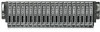
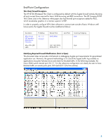
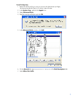
The Implementation VPN Installation This section covers use of a CISCO VPN 3000 appliances in conjunction with a CISCO layer 3 switch to ensure that thin clients and blade PCs meet configuration policy prior to connection with the trusted network segment. The network topology used in this reference implementation is found in Figure 1 below. SYST RPS STAT DUPLX SPEED POE MODE 1 2 1X 3 4 5 6 2X 7 8 9 10 11 12 13 14 15 16 17 18 15X 17X 19 20 21 22 23 24 25 26 27 28 29 30 31 32 33 34 31X 33X 35 36 37 38 39 40 41 42 43 44 45 46 47 48 47X 16X 18X 32X 34X 48X Catalyst 3560 SERIES PoE-48 1 3 2 4 CISCO VPN 3000 Series Concentrator 1 A 3 CONSOLE PRIVATE LINK TX B RESET COLL 100 Private interface 2 4 PUBLIC LINK TX COLL 100 EXTERNAL LINK TX COLL 100 Public interface to Client(crossover cable) HP CCI PC Blade Infrastructure Public Access Clients HP Thin Clients & Blade PCs Figure 1 - Reference VPN topology IP Addresses VPN Private - 10.2.2.1 VPN Public - 10.1.1.1 Switch VLAN 2 - 10.2.2.2 Switch VLAN 3 - 10.3.3.2 Switch VLAN 4 - 10.4.4.2 Switch VLAN 5 - 10.5.5.2 Switch VLAN 6 - 10.6.6.2 The Cisco 3560 switch is configured with VLANs assigned to ports 1 to 5, as shown in Figure 1 above. Full switch configuration settings can be found in Appendix A - CISCO 3560 Switch Configuration. Basic VPN Configuration This paper focuses on the integration of VPN services to HP thin clients and blade PCs. As such, we are exploring only configuration settings that are pertinent to these clients. This does not exhaust all possible VPN configurations, and in a production environment, you may wish to validate many more OS configuration components than are discussed in this reference white paper. For full documentation on the possible setup options for the Cisco VPN3000 appliance, please see VPN 3000 Series Concentrator Reference Volume I: Configuration, Release 4.7 at http://www.cisco.com/en/US/docs/security/vpn3000/vpn3000_47/configuration/config.html. Instructions below step through a basic Virtual-IP VPN configuration from a public network to private LAN. As previously mentioned, the public network is Class-C with scope 10.1.1.x/255. The Cisco VPN3000 Concentrator, like other servers/services on the public interface, has a fixed IP address at 10.1.1.2 and bridges to the private Class C network with scope 10.2.2.x/255. 4
-
 1
1 -
 2
2 -
 3
3 -
 4
4 -
 5
5 -
 6
6 -
 7
7 -
 8
8 -
 9
9 -
 10
10 -
11
-
12
-
13
-
14
-
15
-
16
-
17
-
18
-
19
-
20
-
21
-
22
-
23
-
24
-
25
 |
 |