HP Cisco MDS 9120 Cisco Nexus 5000 Series Hardware Installation Guide (OL-1590
HP Cisco MDS 9120 - Fabric Switch Manual
 |
View all HP Cisco MDS 9120 manuals
Add to My Manuals
Save this manual to your list of manuals |
HP Cisco MDS 9120 manual content summary:
- HP Cisco MDS 9120 | Cisco Nexus 5000 Series Hardware Installation Guide (OL-1590 - Page 1
Send documentation comments to [email protected] Cisco Nexus 5000 Series Hardware Installation Guide November 2008 Americas Headquarters Cisco Systems, Inc. 170 West Tasman Drive San Jose, CA 95134-1706 USA http://www.cisco.com Tel: 408 526-4000 - HP Cisco MDS 9120 | Cisco Nexus 5000 Series Hardware Installation Guide (OL-1590 - Page 2
and used in accordance with the instruction manual, may cause harmful interference to radio ; Changing the Way We Work, Live, Play, and Learn is a service mark; and Access Registrar, Aironet, AsyncOS, Bringing the Meeting To You Series Hardware Installation Guide © 2008 Cisco Systems, Inc. - HP Cisco MDS 9120 | Cisco Nexus 5000 Series Hardware Installation Guide (OL-1590 - Page 3
Module 1-6 N5K-M1008 1-7 Ports 1-8 Power Supply 1-9 Fan Module 1-10 LED Descriptions 1-12 Supported SFP Transceivers 1-14 SFP+ Transceivers 1-14 SFP+ Copper Cables 1-14 SFP Fiber Channel Transceivers 1-15 1-23 Power Supply 1-25 Fan Module 1-26 Cisco Nexus 5000 Series Hardware Installation Guide iii - HP Cisco MDS 9120 | Cisco Nexus 5000 Series Hardware Installation Guide (OL-1590 - Page 4
Contents Send documentation comments to [email protected] LED Descriptions 1-27 Port Level LED's 1-28 Supported SFP Transceivers 1-28 SFP+ Transceivers 1-29 SFP+ Copper Cables 1-29 SFP Fiber Channel Transceivers Shipment 2-26 Cisco Nexus 5000 Series Hardware Installation Guide iv OL-15902-01 - HP Cisco MDS 9120 | Cisco Nexus 5000 Series Hardware Installation Guide (OL-1590 - Page 5
Specifications for Cisco Fibre Channel SFP Transceivers B-4 Environmental Conditions and Power Requirements Specification for SFP Transceivers B-5 OL-15902-01 Cisco Nexus 5000 Series Hardware Installation Guide v - HP Cisco MDS 9120 | Cisco Nexus 5000 Series Hardware Installation Guide (OL-1590 - Page 6
Cable C-2 Cable RJ-45 Connector Pinouts C-2 Console Port C-3 Console Port Pinouts C-3 Supported Power Cords and Plugs C-4 Power Cords C-4 AC Power Cord Illustrations C-5 Jumper Power E-2 Switch Operation Best Practices E-2 E-2 Cisco Nexus 5000 Series Hardware Installation Guide vi OL-15902-01 - HP Cisco MDS 9120 | Cisco Nexus 5000 Series Hardware Installation Guide (OL-1590 - Page 7
must be familiar with electronic circuitry and wiring practices and preferably be an electronic or electromechanical technician. Organization This guide is organized as follows: Chapter Chapter 1 Title Product Overview Chapter 2 Installing the Cisco Nexus 5000 Switch Chapter 3 Connecting the - HP Cisco MDS 9120 | Cisco Nexus 5000 Series Hardware Installation Guide (OL-1590 - Page 8
Troubleshooting Hardware Components Description Provides site planning and maintenance records. Provides installation troubleshooting warning symbol precedes each warning statement. Warning IMPORTANT SAFETY INSTRUCTIONS This warning symbol means danger. You are in a Guide viii OL-15902-01 - HP Cisco MDS 9120 | Cisco Nexus 5000 Series Hardware Installation Guide (OL-1590 - Page 9
sécurité traduites qui accompagnent cet appareil, référez-vous au numéro de l'instruction situé à la fin de chaque avertissement. CONSERVEZ CES INFORMATIONS Warnung WICHTIGE SICHERHEITSHINWEISE TA VARE PÅ DISSE INSTRUKSJONENE OL-15902-01 Cisco Nexus 5000 Series Hardware Installation Guide ix - HP Cisco MDS 9120 | Cisco Nexus 5000 Series Hardware Installation Guide (OL-1590 - Page 10
av varje varning för att hitta dess översättning i de översatta säkerhetsvarningar som medföljer denna anordning. SPARA DESSA ANVISNINGAR Cisco Nexus 5000 Series Hardware Installation Guide x OL-15902-01 - HP Cisco MDS 9120 | Cisco Nexus 5000 Series Hardware Installation Guide (OL-1590 - Page 11
for at finde oversættelsen i de oversatte advarsler, der fulgte med denne enhed. GEM DISSE ANVISNINGER OL-15902-01 Cisco Nexus 5000 Series Hardware Installation Guide xi - HP Cisco MDS 9120 | Cisco Nexus 5000 Series Hardware Installation Guide (OL-1590 - Page 12
Preface Send documentation comments to [email protected] Cisco Nexus 5000 Series Hardware Installation Guide xii OL-15902-01 - HP Cisco MDS 9120 | Cisco Nexus 5000 Series Hardware Installation Guide (OL-1590 - Page 13
Preface Send documentation comments to [email protected] OL-15902-01 Cisco Nexus 5000 Series Hardware Installation Guide xiii - HP Cisco MDS 9120 | Cisco Nexus 5000 Series Hardware Installation Guide (OL-1590 - Page 14
Nexus 5000 Series Troubleshooting Guide • Cisco Nexus 5000 Series XML Management Interface Guide • Cisco Nexus 5000 Series Hardware Installation Guide • Regulatory Compliance and Safety Information for the Cisco Nexus 5000 Series Obtaining Documentation, Obtaining Support, and Security Guidelines - HP Cisco MDS 9120 | Cisco Nexus 5000 Series Hardware Installation Guide (OL-1590 - Page 15
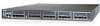
Modules, page 1-5 • Power Supply, page 1-9 • Fan Module, page 1-10 • LED Descriptions, page 1-12 • Supported SFP Transceivers, page 1-14 Features The Cisco Nexus 5020 switch is a 2 RU, top-of-rack switch that provides switch OL-15902-01 Cisco Nexus 5000 Series Hardware Installation Guide 1-1 - HP Cisco MDS 9120 | Cisco Nexus 5000 Series Hardware Installation Guide (OL-1590 - Page 16
View 186260 1 2 1 Two power supplies 2 Five fan modules Figure 1-2 shows a close-up view of the front of the switch. Cisco Nexus 5000 Series Hardware Installation Guide 1-2 OL-15902-01 - HP Cisco MDS 9120 | Cisco Nexus 5000 Series Hardware Installation Guide (OL-1590 - Page 17
management ports on the right (top Ethernet expansion modules and bottom) 3 Console port 6 AC power connectors OL-15902-01 Cisco Nexus 5000 Series Hardware Installation Guide 1-3 - HP Cisco MDS 9120 | Cisco Nexus 5000 Series Hardware Installation Guide (OL-1590 - Page 18
. Figure 1-5 shows a close-up view of the Ethernet connector port. Figure 1-5 Ethernet Connector Port 1 2 186385 1 Internal cross connect ports Cisco Nexus 5000 Series Hardware Installation Guide 1-4 2 Network management ports OL-15902-01 - HP Cisco MDS 9120 | Cisco Nexus 5000 Series Hardware Installation Guide (OL-1590 - Page 19
module with six ports of 10-Gigabit Ethernet Cisco Data Center Ethernet and FCoE The chassis supports hot swapping of the expansion modules. Fibre Channel Plus Ethernet Expansion Module The Fibre Channel Channel plus Ethernet expansion module. Cisco Nexus 5000 Series Hardware Installation Guide 1-5 - HP Cisco MDS 9120 | Cisco Nexus 5000 Series Hardware Installation Guide (OL-1590 - Page 20
plus Ethernet expansion module. Ethernet Expansion Module The Ethernet expansion module supports six 10-Gigabit Ethernet ports, four of which will have encryption capability 1 & 3 Six 10-Gigabit Ethernet ports Cisco Nexus 5000 Series Hardware Installation Guide 1-6 56 2 Module LED OL-15902-01 - HP Cisco MDS 9120 | Cisco Nexus 5000 Series Hardware Installation Guide (OL-1590 - Page 21
ports are grouped and numbered on the Ethernet expansion module. N5K-M1008 The N5K-M1008 GEM supports 8 1/2/4G Fiber Channel, SFP based uplink connection. Figure 1-25 shows the N5K-M1008 GEM 2-, 4-Gbps Fibre Channel ports 2 LED OL-15902-01 Cisco Nexus 5000 Series Hardware Installation Guide 1-7 - HP Cisco MDS 9120 | Cisco Nexus 5000 Series Hardware Installation Guide (OL-1590 - Page 22
how ports are numbered and grouped by function for both the fixed ports and the Ethernet expansion module ports. Cisco Nexus 5000 Series Hardware Installation Guide 1-8 OL-15902-01 - HP Cisco MDS 9120 | Cisco Nexus 5000 Series Hardware Installation Guide (OL-1590 - Page 23
one for failure condition. Figure 1-13 Power Supply for the Cisco Nexus 5020 Switch 186264 OL-15902-01 12 Cisco Nexus 5000 Series Hardware Installation Guide 1-9 - HP Cisco MDS 9120 | Cisco Nexus 5000 Series Hardware Installation Guide (OL-1590 - Page 24
186854 Fan Module The Cisco Nexus 5020 switch has five fans modules. Figure 1-15 shows the fan module. 1-10 Cisco Nexus 5000 Series Hardware Installation Guide OL-15902-01 - HP Cisco MDS 9120 | Cisco Nexus 5000 Series Hardware Installation Guide (OL-1590 - Page 25
fan module LED indicates fan tray health. Green indicates normal operation, while amber indicates a fan failure. OL-15902-01 Cisco Nexus 5000 Series Hardware Installation Guide 1-11 - HP Cisco MDS 9120 | Cisco Nexus 5000 Series Hardware Installation Guide (OL-1590 - Page 26
to blink and the module does not come online. The module has runtime failure and is brought offline. 1-12 Cisco Nexus 5000 Series Hardware Installation Guide OL-15902-01 - HP Cisco MDS 9120 | Cisco Nexus 5000 Series Hardware Installation Guide (OL-1590 - Page 27
the CLI command or the module is initializing. The port is faulty and has been disabled. OL-15902-01 Cisco Nexus 5000 Series Hardware Installation Guide 1-13 - HP Cisco MDS 9120 | Cisco Nexus 5000 Series Hardware Installation Guide (OL-1590 - Page 28
on the electrical interface and duplex LC connector on the optical interface.The Cisco Nexus 5020 switch supports the SFP-10G-SR transceiver. Model SFP-10G-SR Description 10-Gigabit Ethernet-short range SFP+ AWG • 7m, 24-26 AWG 1-14 Cisco Nexus 5000 Series Hardware Installation Guide OL-15902-01 - HP Cisco MDS 9120 | Cisco Nexus 5000 Series Hardware Installation Guide (OL-1590 - Page 29
Meter SFP Fiber Channel Transceivers The Cisco Nexus 5020 switch also supports the following SFP Fibre Channel transceiver: Model DS-SFP-FC4G-SW • Fan Module, page 1-26 • LED Descriptions, page 1-27 • Supported SFP Transceivers, page 1-28 OL-15902-01 Cisco Nexus 5000 Series Hardware Installation - HP Cisco MDS 9120 | Cisco Nexus 5000 Series Hardware Installation Guide (OL-1590 - Page 30
shows the front of the Cisco Nexus 5010 switch. Figure 1-17 Cisco Nexus 5010 Switch Front View 189949 1 2 1-16 Cisco Nexus 5000 Series Hardware Installation Guide OL-15902-01 - HP Cisco MDS 9120 | Cisco Nexus 5000 Series Hardware Installation Guide (OL-1590 - Page 31
rear of the Cisco Nexus 5010 switch. Figure 1-19 Cisco Nexus 5010 Switch Rear View 1 2 3 4 5 6 189951 OL-15902-01 Cisco Nexus 5000 Series Hardware Installation Guide 1-17 - HP Cisco MDS 9120 | Cisco Nexus 5000 Series Hardware Installation Guide (OL-1590 - Page 32
and bottom), and two network management ports on the right (top and bottom) 3 Console port 6 AC power connectors 1-18 Cisco Nexus 5000 Series Hardware Installation Guide OL-15902-01 - HP Cisco MDS 9120 | Cisco Nexus 5000 Series Hardware Installation Guide (OL-1590 - Page 33
Ethernet connector port. Figure 1-21 Ethernet Connector Port 1 2 186385 1 Internal cross connect ports 2 Network management ports OL-15902-01 Cisco Nexus 5000 Series Hardware Installation Guide 1-19 - HP Cisco MDS 9120 | Cisco Nexus 5000 Series Hardware Installation Guide (OL-1590 - Page 34
Fiber Channel, SFP based uplink connection. The chassis supports hot swapping of the expansion modules. N5K-M1404 The N5K-M1404 GEM supports four SFP+ transceiver modules and four 1-, 2-, 4-Gbps Gatos Expansion Module 186384 1-20 Cisco Nexus 5000 Series Hardware Installation Guide OL-15902-01 - HP Cisco MDS 9120 | Cisco Nexus 5000 Series Hardware Installation Guide (OL-1590 - Page 35
186258 1 23 4 1 23 4 2 N5K-M1600 1 Four 10-Gigabit Ethernet ports 2 Module LED 3 Four 1-, 2-, 4-Gbps Fibre Channel ports The N5K-M1600 GEM supports 6 10G SFP+ based uplink connections. Figure 1-24 shows the N5K-M1600 GEM. Figure 1-24 N5K-M1600 GEM 1 3 10 GIGABIT ETHERNET 186259 1 23 - HP Cisco MDS 9120 | Cisco Nexus 5000 Series Hardware Installation Guide (OL-1590 - Page 36
are grouped and numbered on the Ethernet expansion module. N5K-M1008 The N5K-M1008 GEM supports 8 1/2/4G Fiber Channel, SFP based uplink connection. Figure 1-25 shows the N5K-M1008 2-, 4-Gbps Fibre Channel ports 2 LED 1-22 Cisco Nexus 5000 Series Hardware Installation Guide 189954 OL-15902-01 - HP Cisco MDS 9120 | Cisco Nexus 5000 Series Hardware Installation Guide (OL-1590 - Page 37
1-28 shows how ports are numbered and grouped by function with the N5K-M1600 GEM installed. OL-15902-01 Cisco Nexus 5000 Series Hardware Installation Guide 1-23 - HP Cisco MDS 9120 | Cisco Nexus 5000 Series Hardware Installation Guide (OL-1590 - Page 38
configured with the N5K-M1008 GEM A B C D 1 3 5 7 1 2 4 6 8 9 11 13 15 10 12 14 16 17 19 2 18 20 1 3 5 7 2 4 6 8 192243 1-24 Cisco Nexus 5000 Series Hardware Installation Guide OL-15902-01 - HP Cisco MDS 9120 | Cisco Nexus 5000 Series Hardware Installation Guide (OL-1590 - Page 39
, including over voltage, over current, Off over temperature, and fan failure. Fail LED Status Off On OL-15902-01 Cisco Nexus 5000 Series Hardware Installation Guide 1-25 - HP Cisco MDS 9120 | Cisco Nexus 5000 Series Hardware Installation Guide (OL-1590 - Page 40
per module and 2-modules provides the switch with a total of 12-fans.Figure 1-32 shows the fan module. 1-26 Cisco Nexus 5000 Series Hardware Installation Guide OL-15902-01 - HP Cisco MDS 9120 | Cisco Nexus 5000 Series Hardware Installation Guide (OL-1590 - Page 41
color) Amber Solid On Fan tray operating normally Solid On Fan failure within the fan tray OL-15902-01 Cisco Nexus 5000 Series Hardware Installation Guide 1-27 - HP Cisco MDS 9120 | Cisco Nexus 5000 Series Hardware Installation Guide (OL-1590 - Page 42
Notes Depending on the product you look at, the LED could be off, or solid amber. Blinks based on network activity Supported SFP Transceivers The Cisco Nexus 5010 switch supports both SFP+ Ethernet transceivers and SFP Fibre Channel transceivers. 1-28 Cisco Nexus 5000 Series Hardware Installation - HP Cisco MDS 9120 | Cisco Nexus 5000 Series Hardware Installation Guide (OL-1590 - Page 43
and duplex LC connector on the optical interface.The Cisco Nexus 5010 switch supports the following SFP+ optical transceivers: • SR • DCR, SR-Lite SFP+ Cable 7 Meter SFP Fiber Channel Transceivers The Cisco Nexus 5010 switch supports the multimode 850nm 4Gbps SFP with 150m reach. Model DS-SFP-FC4G- - HP Cisco MDS 9120 | Cisco Nexus 5000 Series Hardware Installation Guide (OL-1590 - Page 44
Nexus 5010 Switch Chapter 1 Product Overview Send documentation comments to [email protected] 1-30 Cisco Nexus 5000 Series Hardware Installation Guide OL-15902-01 - HP Cisco MDS 9120 | Cisco Nexus 5000 Series Hardware Installation Guide (OL-1590 - Page 45
service the system, read the Regulatory Compliance and Safety Information for the Cisco Nexus 5000 Family for important safety information. Warning IMPORTANT SAFETY INSTRUCTIONS Statement 1071 SAVE THESE INSTRUCTIONS Warning This unit service this equipment. Statement 1030 OL-15902-01 - HP Cisco MDS 9120 | Cisco Nexus 5000 Series Hardware Installation Guide (OL-1590 - Page 46
licensing, see the Cisco Nexus 5000 Series CLI Configuration Guide. Preparing for Installation This section includes the following topics: - The EIA Shelf Bracket Kit (an optional kit, purchased separately) For instructions on installing the switch using the rack-mount kit shipped with the switch, - HP Cisco MDS 9120 | Cisco Nexus 5000 Series Hardware Installation Guide (OL-1590 - Page 47
configure the switch. • Ensure that there is adequate space around the switch to allow for servicing the switch and for adequate airflow (Appendix B, "Technical Specifications," lists airflow requirements). • Ensure and breakers. OL-15902-01 Cisco Nexus 5000 Series Hardware Installation Guide 2-3 - HP Cisco MDS 9120 | Cisco Nexus 5000 Series Hardware Installation Guide (OL-1590 - Page 48
during transportation or any items are missing, contact your customer service representative immediately. To inspect the shipment, follow these steps: Compare the shipment to the equipment list provided by your customer service representative and verify that you have received all items, including - HP Cisco MDS 9120 | Cisco Nexus 5000 Series Hardware Installation Guide (OL-1590 - Page 49
Check for damage and report any discrepancies or damage to your customer service representative. Have the following information ready: • Invoice number of Rack-mount brackets M4x0.7 x 8-mm Phillips countersunk screws Rack-mount guides 10-32 Rack Nuts 10-32 x 3/4-inch Phillips countersunk screws - HP Cisco MDS 9120 | Cisco Nexus 5000 Series Hardware Installation Guide (OL-1590 - Page 50
Figure 2-1 Attaching Front Rack-Mount Bracket to the Cisco Nexus 5020 switch 186363 2 3 1 1 Front rack-mount bracket 2 Rack-mount guides 3 Slider rail Step 2 Install the rack-mount guides on the switch as follows: a. Position one of the rack-mount brackets against the side of the switch and - HP Cisco MDS 9120 | Cisco Nexus 5000 Series Hardware Installation Guide (OL-1590 - Page 51
switch with the back of the switch between the front posts of the rack. b. Align the two rack-mount guides on either side of the switch with the slider rails installed in the rack. Slide the rack-mount glides onto the Rack 186413 OL-15902-01 Cisco Nexus 5000 Series Hardware Installation Guide 2-7 - HP Cisco MDS 9120 | Cisco Nexus 5000 Series Hardware Installation Guide (OL-1590 - Page 52
. Table 2-2 Cisco Nexus 5010 Switch Rack-Mount Kit Quantity 2 12 2 10 10 2 Part Description Rack-mount brackets M4x0.7 x 8-mm Phillips countersunk screws Rack-mount guides 10-32 Rack Nuts 10-32 x 3/4-inch Phillips countersunk screws Slider rails Cisco Nexus 5000 Series Hardware Installation - HP Cisco MDS 9120 | Cisco Nexus 5000 Series Hardware Installation Guide (OL-1590 - Page 53
Figure 2-5 Attaching Front Rack-Mount Bracket to the Cisco Nexus 5010 switch 273161 3 2 1 1 Front rack-mount bracket 2 Rack-mount guides 3 Slider rail Step 2 Install the rack-mount guides on the switch as follows: a. Position one of the rack-mount brackets against the side of the switch and - HP Cisco MDS 9120 | Cisco Nexus 5000 Series Hardware Installation Guide (OL-1590 - Page 54
the back of the switch between the front posts of the rack. b. Align the two rack-mount guides on either side of the switch with the slider rails installed in the rack. Slide the rack-mount grounding practice guidelines. 2-10 Cisco Nexus 5000 Series Hardware Installation Guide OL-15902-01 - HP Cisco MDS 9120 | Cisco Nexus 5000 Series Hardware Installation Guide (OL-1590 - Page 55
noise. This building contains a standard office environment. Electromagnetic noise problems are not anticipated, but installing a grounding system in a new This building contains a standard office environment. Electromagnetic noise problems are not anticipated, but installing a grounding system - HP Cisco MDS 9120 | Cisco Nexus 5000 Series Hardware Installation Guide (OL-1590 - Page 56
install the system ground lug. See "Establishing the System Ground" section on page 2-14 for installation instructions and location of the chassis system ground pads. Note You do not need to attach a supplemental bare skin. 2-12 Cisco Nexus 5000 Series Hardware Installation Guide OL-15902-01 - HP Cisco MDS 9120 | Cisco Nexus 5000 Series Hardware Installation Guide (OL-1590 - Page 57
ground connector OL-15902-01 186482 1 2 3 4 3 Side view of grounding lug (clip slid behind screw) 4 Clip installed (behind screw) Cisco Nexus 5000 Series Hardware Installation Guide 2-13 - HP Cisco MDS 9120 | Cisco Nexus 5000 Series Hardware Installation Guide (OL-1590 - Page 58
system ground, you need the following tools and materials: • Grounding lug-A two-hole standard barrel lug. Supports up to 6 AWG wire. Supplied as part of accessory kit. • Grounding screws-Two M4 x 8mm . 1 Phillips screwdriver. 2-14 Cisco Nexus 5000 Series Hardware Installation Guide OL-15902-01 - HP Cisco MDS 9120 | Cisco Nexus 5000 Series Hardware Installation Guide (OL-1590 - Page 59
cables used to provide power to the chassis must be the grounding type, and the grounding conductors should connect to protective earth ground at the service equipment. OL-15902-01 Cisco Nexus 5000 Series Hardware Installation - HP Cisco MDS 9120 | Cisco Nexus 5000 Series Hardware Installation Guide (OL-1590 - Page 60
end of the grounding lug. Use the crimping tool to secure the grounding cable in the grounding lug. 2-16 Cisco Nexus 5000 Series Hardware Installation Guide OL-15902-01 - HP Cisco MDS 9120 | Cisco Nexus 5000 Series Hardware Installation Guide (OL-1590 - Page 61
connect the Ethernet port to the LAN until the initial switch configuration has been performed. For instructions on configuring the switch, see the Cisco Nexus 5000 Series CLI Configuration Guide. For instructions on connecting to the console port, see the "Connecting to the Console Port" section on - HP Cisco MDS 9120 | Cisco Nexus 5000 Series Hardware Installation Guide (OL-1590 - Page 62
has booted and the switch has initialized without error messages. If any problems occur, see Appendix E, "Troubleshooting Hardware Components". If you cannot resolve an issue, contact your customer service representative. Complete the worksheets provided in Appendix D, "Site Planning and Maintenance - HP Cisco MDS 9120 | Cisco Nexus 5000 Series Hardware Installation Guide (OL-1590 - Page 63
install an expansion module, follow these steps: Step 1 Step 2 Step 3 Grasp the handle of the module and place your other hand under the module to support it. Gently slide the module into the opening until you cannot push it any further. Tighten the captive screw on the front of the module - HP Cisco MDS 9120 | Cisco Nexus 5000 Series Hardware Installation Guide (OL-1590 - Page 64
5010 Chassis 273162 Removing an Expansion Module To remove an expansion module from the chassis, follow these steps: 2-20 Cisco Nexus 5000 Series Hardware Installation Guide OL-15902-01 - HP Cisco MDS 9120 | Cisco Nexus 5000 Series Hardware Installation Guide (OL-1590 - Page 65
slot. Place your other hand under the module to support the weight of it. Do not touch the module and Installing Power Supplies The Cisco Nexus 5000 switch supports two front-end power supplies, but it may be power supply to support it while you slide it out of the chassis. OL - HP Cisco MDS 9120 | Cisco Nexus 5000 Series Hardware Installation Guide (OL-1590 - Page 66
273163 Installing a Power Supply To install a power supply, follow these steps: Step 1 Ensure that the system (earth) ground connection has been made. For ground connection instructions, see the "Grounding the System" section on page 2-10. 2-22 Cisco Nexus 5000 Series Hardware Installation - HP Cisco MDS 9120 | Cisco Nexus 5000 Series Hardware Installation Guide (OL-1590 - Page 67
: • Figure 2-14Fan Module for the Cisco Nexus 5010 switch, page 2-24 • Installing a Fan Module, page 2-25 OL-15902-01 Cisco Nexus 5000 Series Hardware Installation Guide 2-23 - HP Cisco MDS 9120 | Cisco Nexus 5000 Series Hardware Installation Guide (OL-1590 - Page 68
the spinning fan blades. Let the fan blades completely stop before you remove the fan tray. Statement 258 2-24 Cisco Nexus 5000 Series Hardware Installation Guide OL-15902-01 - HP Cisco MDS 9120 | Cisco Nexus 5000 Series Hardware Installation Guide (OL-1590 - Page 69
occurs, contact your customer service representative for a replacement part. Note If you purchased this product through a Cisco reseller, contact the reseller directly for technical support. If you purchased this mounting rails. OL-15902-01 Cisco Nexus 5000 Series Hardware Installation Guide 2-25 - HP Cisco MDS 9120 | Cisco Nexus 5000 Series Hardware Installation Guide (OL-1590 - Page 70
on page 2-25, and repack it for shipment. If possible, use the original packing materials and container to repack the switch. Contact your Cisco customer service representative to arrange for return shipment to Cisco. 2-26 Cisco Nexus 5000 Series Hardware Installation - HP Cisco MDS 9120 | Cisco Nexus 5000 Series Hardware Installation Guide (OL-1590 - Page 71
Ethernet Connector Port, page 3-3 • Connecting to an Ethernet Port, page 3-4 • Connecting to a Fibre Channel Port, page 3-7 OL-15902-01 Cisco Nexus 5000 Series Hardware Installation Guide 3-1 - HP Cisco MDS 9120 | Cisco Nexus 5000 Series Hardware Installation Guide (OL-1590 - Page 72
the console port to perform the following: • Configure the Cisco Nexus 5000 switch from the CLI. • Monitor network statistics and errors. • Configure SNMP agent parameters. • Download software updates. Cisco Nexus 5000 Series Hardware Installation Guide 3-2 OL-15902-01 - HP Cisco MDS 9120 | Cisco Nexus 5000 Series Hardware Installation Guide (OL-1590 - Page 73
parameters. • Download software updates. Note To connect the console port to a computer terminal, the computer must support VT100 terminal computer serial port. Note For configuration instructions, see the Cisco Nexus 5000 Series CLI Configuration Guide. Connecting to the Ethernet Connector Port - HP Cisco MDS 9120 | Cisco Nexus 5000 Series Hardware Installation Guide (OL-1590 - Page 74
Step 2 Step 3 Step 4 Attach an ESD-preventive wrist strap and follow its instructions for use. Remove the dust cover from the port cage. Remove the dust Step 1 Step 2 Attach an ESD-preventive wrist strap and follow its instructions for use. If a cable is installed in the transceiver: a. Record - HP Cisco MDS 9120 | Cisco Nexus 5000 Series Hardware Installation Guide (OL-1590 - Page 75
factory. If another transceiver is not being installed, protect the optical cage by inserting a clean cover. OL-15902-01 Cisco Nexus 5000 Series Hardware Installation Guide 3-5 - HP Cisco MDS 9120 | Cisco Nexus 5000 Series Hardware Installation Guide (OL-1590 - Page 76
If the cable does not install easily, ensure that it is correctly positioned before continuing. For instructions on verifying connectivity, see the Cisco Nexus 5000 Switch Configuration Guide. Removing a Cable from an SFP+ Transceiver Caution When pulling a cable from a transceiver, grip the body - HP Cisco MDS 9120 | Cisco Nexus 5000 Series Hardware Installation Guide (OL-1590 - Page 77
an SFP transceiver. Installing an SFP Transceiver To install an SFP transceiver, follow these steps: Step 1 Attach an ESD-preventive wrist strap and follow its instructions for use. OL-15902-01 Cisco Nexus 5000 Series Hardware Installation - HP Cisco MDS 9120 | Cisco Nexus 5000 Series Hardware Installation Guide (OL-1590 - Page 78
transceiver, follow these steps: Step 1 Step 2 Attach an ESD-preventive wrist strap and follow its instructions for use. If a cable is installed in the transceiver: a. Record the cable and port port cage during this process. Cisco Nexus 5000 Series Hardware Installation Guide 3-8 OL-15902-01 - HP Cisco MDS 9120 | Cisco Nexus 5000 Series Hardware Installation Guide (OL-1590 - Page 79
follow these steps: Step 1 Step 2 Step 3 Step 4 Attach an ESD-preventive wrist strap and follow its instructions for use. Remove the dust cover from the connector on the cable. Remove the dust cover from the cable Figure 3-4). OL-15902-01 Cisco Nexus 5000 Series Hardware Installation Guide 3-9 - HP Cisco MDS 9120 | Cisco Nexus 5000 Series Hardware Installation Guide (OL-1590 - Page 80
the cable does not install easily, ensure that it is correctly positioned before continuing. For instructions on verifying connectivity, see the Cisco Nexus 5000 Series CLI Configuration Guide. Removing a Cable from an SFP Transceiver Caution When pulling a cable from a transceiver, grip the body - HP Cisco MDS 9120 | Cisco Nexus 5000 Series Hardware Installation Guide (OL-1590 - Page 81
is suspected, clean and then inspect fiber ends under a microscope to determine if damage has occurred. OL-15902-01 Cisco Nexus 5000 Series Hardware Installation Guide 3-11 - HP Cisco MDS 9120 | Cisco Nexus 5000 Series Hardware Installation Guide (OL-1590 - Page 82
Connecting to a Fibre Channel Port Chapter 3 Connecting the Cisco Nexus 5000 Switch Send documentation comments to [email protected] 3-12 Cisco Nexus 5000 Series Hardware Installation Guide OL-15902-01 - HP Cisco MDS 9120 | Cisco Nexus 5000 Series Hardware Installation Guide (OL-1590 - Page 83
rack space per 5020 chassis must be two RU (rack units), equal to 3.50 inches (8.9 cm). OL-15902-01 Cisco Nexus 5000 Series Hardware Installation Guide A-1 - HP Cisco MDS 9120 | Cisco Nexus 5000 Series Hardware Installation Guide (OL-1590 - Page 84
: PS-DK/OEM Cabinet Assembly, (78.7 in.) 1998 mm X 23.6 in. (600 mm) X 39.4 in. (1000 mm) (H x W x D) (42 RU) Cisco Nexus 5000 Series Hardware Installation Guide A-2 OL-15902-01 - HP Cisco MDS 9120 | Cisco Nexus 5000 Series Hardware Installation Guide (OL-1590 - Page 85
make it easier to route as many as 56 fiber or copper cables through the rack. OL-15902-01 Cisco Nexus 5000 Series Hardware Installation Guide A-3 - HP Cisco MDS 9120 | Cisco Nexus 5000 Series Hardware Installation Guide (OL-1590 - Page 86
Cable Management Guidelines Appendix A Cabinet and Rack Installation Send documentation comments to [email protected] Cisco Nexus 5000 Series Hardware Installation Guide A-4 OL-15902-01 - HP Cisco MDS 9120 | Cisco Nexus 5000 Series Hardware Installation Guide (OL-1590 - Page 87
) 35 lb (15.875 kg) Table B-3 lists the environmental specifications for the Cisco Nexus 5000 switch. OL-15902-01 Cisco Nexus 5000 Series Hardware Installation Guide B-1 - HP Cisco MDS 9120 | Cisco Nexus 5000 Series Hardware Installation Guide (OL-1590 - Page 88
to 60 Hz Maximum = 63 Hz 750 W 480 W 12 V 1.57 in (0.039m) x 4.00 in (0.101m) x 13.00 in (.330m) Cisco Nexus 5000 Series Hardware Installation Guide B-2 OL-15902-01 - HP Cisco MDS 9120 | Cisco Nexus 5000 Series Hardware Installation Guide (OL-1590 - Page 89
label for 200-240V. However, it has since been certified to support 110V input as well. As a result, both 110V and 220V inputs are supported and the labels on the chassis moving forwards will reflect this capability. Amber) Off On OL-15902-01 Cisco Nexus 5000 Series Hardware Installation Guide B-3 - HP Cisco MDS 9120 | Cisco Nexus 5000 Series Hardware Installation Guide (OL-1590 - Page 90
Cisco Fibre Channel SFP Transceivers Table B-10 lists the general specifications for Cisco Fibre Channel SFP transceivers at 4 Gbps. Cisco Nexus 5000 Series Hardware Installation Guide B-4 OL-15902-01 - HP Cisco MDS 9120 | Cisco Nexus 5000 Series Hardware Installation Guide (OL-1590 - Page 91
occur over an extended period of time between absolute maximum ratings and the recommended operating conditions. OL-15902-01 Cisco Nexus 5000 Series Hardware Installation Guide B-5 - HP Cisco MDS 9120 | Cisco Nexus 5000 Series Hardware Installation Guide (OL-1590 - Page 92
Transceiver Specifications Appendix B Technical Specifications Send documentation comments to [email protected] Cisco Nexus 5000 Series Hardware Installation Guide B-6 OL-15902-01 - HP Cisco MDS 9120 | Cisco Nexus 5000 Series Hardware Installation Guide (OL-1590 - Page 93
Switch, page C-1 • Console Port, page C-3 • Supported Power Cords and Plugs, page C-4 • Jumper Power items: • 2 slider rails • 2 rack-mount guides • 2 rack-mount brackets • 16 M4 x 0.7 Additional parts can be ordered from your customer service representative. Accessory Kit for the Cisco Nexus 5010 - HP Cisco MDS 9120 | Cisco Nexus 5000 Series Hardware Installation Guide (OL-1590 - Page 94
ground lug kit • 1 ESD wrist strap Note Additional parts can be ordered from your customer service representative. Console Cable The console cable has a RJ-45, RS-232 connector on one end 3 Signal Name CTS DSR ZXD GND GND TXD Cisco Nexus 5000 Series Hardware Installation Guide C-2 OL-15902-01 - HP Cisco MDS 9120 | Cisco Nexus 5000 Series Hardware Installation Guide (OL-1590 - Page 95
5010 switch. Table C-3 Console Port Pinouts Pin Signal 1 RTS 2 DTR 3 TxD 4 GND 5 GND 6 RxD 7 DSR 8 CTS OL-15902-01 Cisco Nexus 5000 Series Hardware Installation Guide C-3 - HP Cisco MDS 9120 | Cisco Nexus 5000 Series Hardware Installation Guide (OL-1590 - Page 96
Only the regular power cords or jumper power cords provided with the switch are supported. Table C-4 lists the power cords for the Cisco Nexus 5020 switch and C-5 2.5 Figure C-6 2.5 Figure C-7 2.5 Figure C-8 2.5 Figure C-9 Cisco Nexus 5000 Series Hardware Installation Guide C-4 OL-15902-01 - HP Cisco MDS 9120 | Cisco Nexus 5000 Series Hardware Installation Guide (OL-1590 - Page 97
Appendix C Cable and Port Specifications Supported Power Cords and Plugs Send documentation comments to [email protected] Table C-4 Power Cords for the Cisco V MAX Length: 8.2 ft Connector: EL 701 (IEC60320/C13) 186571 OL-15902-01 Cisco Nexus 5000 Series Hardware Installation Guide C-5 - HP Cisco MDS 9120 | Cisco Nexus 5000 Series Hardware Installation Guide (OL-1590 - Page 98
Supported Power Cords and Plugs Appendix C Cable and Port Specifications Send documentation comments to [email protected] Figure C-3 Cordset rating: 10A/16 A, 250 V Length: 8 ft 2 in. (2.5 m) Connector: VSCC15 186576 Cisco Nexus 5000 Series Hardware Installation Guide C-6 OL-15902-01 - HP Cisco MDS 9120 | Cisco Nexus 5000 Series Hardware Installation Guide (OL-1590 - Page 99
Appendix C Cable and Port Specifications Supported Power Cords and Plugs Send documentation comments to [email protected] Figure C-6 SFS-250V-10A-ID Length: 8 ft 2 in. (2.5 m) Connector C15M (EN60320/C15 ) 186574 113375 OL-15902-01 Cisco Nexus 5000 Series Hardware Installation Guide C-7 - HP Cisco MDS 9120 | Cisco Nexus 5000 Series Hardware Installation Guide (OL-1590 - Page 100
Supported Power Cords and Plugs Appendix C Cable and Port Specifications Send documentation comments to [email protected] Figure C-9 CAB-9K10A- ) (79±2m) Figure C-12 CAB-N5K6A-NA Connector: EL 701 (IEC60320/C13) 186568 Cisco Nexus 5000 Series Hardware Installation Guide C-8 OL-15902-01 - HP Cisco MDS 9120 | Cisco Nexus 5000 Series Hardware Installation Guide (OL-1590 - Page 101
Appendix C Cable and Port Specifications Supported Power Cords and Plugs Send documentation comments to [email protected] 186570 Plug: NEMA 6-15P Cordset rating: 10 A, 250 Figure C-15 CAB-IND-10A Connector: HS10S 186569 OL-15902-01 Cisco Nexus 5000 Series Hardware Installation Guide C-9 - HP Cisco MDS 9120 | Cisco Nexus 5000 Series Hardware Installation Guide (OL-1590 - Page 102
C-16 CAB-C13-C14-JMPR, Jumper Power Cord Plug: SS10A Cordset rating 10A, 250V (686mm) Connector: HS10S 186569 C-10 Cisco Nexus 5000 Series Hardware Installation Guide OL-15902-01 - HP Cisco MDS 9120 | Cisco Nexus 5000 Series Hardware Installation Guide (OL-1590 - Page 103
to query the switch for configuration information, see the Cisco Nexus 5000 Switch Configuration Guide. Site Preparation Checklist Planning the location and layout of your equipment rack or wiring B-2 for power and heat ratings. OL-15902-01 Cisco Nexus 5000 Series Hardware Installation Guide D-1 - HP Cisco MDS 9120 | Cisco Nexus 5000 Series Hardware Installation Guide (OL-1590 - Page 104
1. Verify that the power supply installed in the chassis has a dedicated AC source circuit. 2. UPS = uninterruptible power supply. Date Cisco Nexus 5000 Series Hardware Installation Guide D-2 OL-15902-01 - HP Cisco MDS 9120 | Cisco Nexus 5000 Series Hardware Installation Guide (OL-1590 - Page 105
/site name Data center location Floor location Address (line 1) Address (line 2) City State Zip code Country OL-15902-01 Cisco Nexus 5000 Series Hardware Installation Guide D-3 - HP Cisco MDS 9120 | Cisco Nexus 5000 Series Hardware Installation Guide (OL-1590 - Page 106
Slot Module Type 1 Supervisor 2 Module Serial Number Notes Note The supervisor module and the interface module are not removable. Cisco Nexus 5000 Series Hardware Installation Guide D-4 OL-15902-01 - HP Cisco MDS 9120 | Cisco Nexus 5000 Series Hardware Installation Guide (OL-1590 - Page 107
E-1 • Switch Hardware Best Practices, page E-1 Overview The key to success when troubleshooting the system hardware is to isolate the problem to a specific system component. The first step is to compare what the system topics: OL-15902-01 Cisco Nexus 5000 Series Hardware Installation Guide E-1 - HP Cisco MDS 9120 | Cisco Nexus 5000 Series Hardware Installation Guide (OL-1590 - Page 108
Appendix E Troubleshooting Hardware Components Send documentation comments to [email protected] the • The system software boots successfully. See the Cisco Nexus 5020 CLI Configuration Guide for information about booting the system and initial configuration task. Switch Operation Best Practices - HP Cisco MDS 9120 | Cisco Nexus 5000 Series Hardware Installation Guide (OL-1590 - Page 109
1-25 power supply LED descriptions 1-9, 1-25 rear view 1-3, 1-17 removing from a rack (procedure) 2-25 repacking for return 2-26 supported SFP transceivers 1-14, 1-28 system ground location (figure) 2-16 console port connecting (figure) 3-2, 3-3 connecting (procedure) 3-3 pinouts C-3 contact and - HP Cisco MDS 9120 | Cisco Nexus 5000 Series Hardware Installation Guide (OL-1590 - Page 110
(figure) 2-13 best practices 2-10 chassis 2-15 establishing the system ground 2-14 tools and equipment to connect the system ground 2-14 guides rack-mount 2-6, 2-9 L LC-type cables connecting to Fibre Channel ports 3-10 LED descriptions power supplies B-3 switch 1-12, 1-27 N network connections - HP Cisco MDS 9120 | Cisco Nexus 5000 Series Hardware Installation Guide (OL-1590 - Page 111
com length C-4 supported power cords (figure) C-5 supported power cords (table) C-4 power plugs supported power plugs cable (procedure) 3-10 specifications B-4 supported 1-14, 1-28 site planning checklist D-2 T transceivers, supported SFPs. See SFP transceivers troubleshooting best practices E-1 - HP Cisco MDS 9120 | Cisco Nexus 5000 Series Hardware Installation Guide (OL-1590 - Page 112
Index Send documentation comments to [email protected] IN-4 Cisco 5000 Series Hardware Installation Guide OL-15902-01
-
 1
1 -
 2
2 -
 3
3 -
 4
4 -
 5
5 -
 6
6 -
 7
7 -
8
-
9
-
10
-
11
-
12
-
13
-
14
-
15
-
16
-
17
-
18
-
19
-
20
-
21
-
22
-
23
-
24
-
25
-
26
-
27
-
28
-
29
-
30
-
31
-
32
-
33
-
34
-
35
-
36
-
37
-
38
-
39
-
40
-
41
-
42
-
43
-
44
-
45
-
46
-
47
-
48
-
49
-
50
-
51
-
52
-
53
-
54
-
55
-
56
-
57
-
58
-
59
-
60
-
61
-
62
-
63
-
64
-
65
-
66
-
67
-
68
-
69
-
70
-
71
-
72
-
73
-
74
-
75
-
76
-
77
-
78
-
79
-
80
-
81
-
82
-
83
-
84
-
85
-
86
-
87
-
88
-
89
-
90
-
91
-
92
-
93
-
94
-
95
-
96
-
97
-
98
-
99
-
100
-
101
-
102
-
103
-
104
-
105
-
106
-
107
-
108
-
109
-
110
-
111
-
112
 |
 |

Send documentation comments to [email protected]
Americas Headquarters
Cisco Systems, Inc.
170 West Tasman Drive
San Jose, CA 95134-1706
USA
Tel: 408 526-4000
800 553-NETS (6387)
Fax: 408 527-0883
Cisco Nexus 5000 Series Hardware
Installation Guide
November 2008
Text Part Number: OL-15902-01