HP Cisco MDS 9120 Cisco Nexus 5000 Series Hardware Installation Guide (OL-1590 - Page 60
Location of System Ground on a Cisco Nexus 5000 Switch, Warning, Caution, Step 1
 |
View all HP Cisco MDS 9120 manuals
Add to My Manuals
Save this manual to your list of manuals |
Page 60 highlights
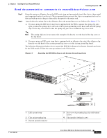
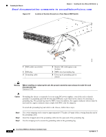
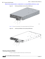
Grounding the Chassis Chapter 2 Installing the Cisco Nexus 5000 Switch Send documentation comments to [email protected] Figure 2-8 Location of System Ground on a Cisco Nexus 5000 Switch 186483 2 1 3 6 1 ESD socket (on switch) 2 ESD plug 3 Grounding cable 5 4 4 Screws, M4, with square cone washers 5 NRTL listed grounding lug 6 Close-up of grounding pad on switch Warning When installing or replacing the unit, the ground connection must always be made first and disconnected last. Statement 1046 Caution Grounding the chassis is required if you are using DC power supplies, even if the rack is already grounded. A grounding pad with two threaded M4 holes is provided on the chassis for attaching a grounding lug. The ground lug must be NRTL listed. In addition, the copper conductor (wires) must be used and the copper conductor must comply with NEC code for ampacity. To attach the grounding lug and cable to the chassis, follow these steps: Step 1 Step 2 Step 3 Use a wire-stripping tool to remove approximately 0.75 inches (19 mm) of the covering from the end of the grounding cable. Insert the stripped end of the grounding cable into the open end of the grounding lug. Use the crimping tool to secure the grounding cable in the grounding lug. 2-16 Cisco Nexus 5000 Series Hardware Installation Guide OL-15902-01
-
 1
1 -
2
-
3
-
4
-
5
-
6
-
7
-
8
-
9
-
10
-
11
-
12
-
13
-
14
-
15
-
16
-
17
-
18
-
19
-
20
-
21
-
22
-
23
-
24
-
25
-
26
-
27
-
28
-
29
-
30
-
31
-
32
-
33
-
34
-
35
-
36
-
37
-
38
-
39
-
40
-
41
-
42
-
43
-
44
-
45
-
46
-
47
-
48
-
49
-
50
-
51
-
52
-
53
-
54
-
 55
55 -
 56
56 -
 57
57 -
 58
58 -
 59
59 -
 60
60 -
 61
61 -
 62
62 -
 63
63 -
 64
64 -
 65
65 -
66
-
67
-
68
-
69
-
70
-
71
-
72
-
73
-
74
-
75
-
76
-
77
-
78
-
79
-
80
-
81
-
82
-
83
-
84
-
85
-
86
-
87
-
88
-
89
-
90
-
91
-
92
-
93
-
94
-
95
-
96
-
97
-
98
-
99
-
100
-
101
-
102
-
103
-
104
-
105
-
106
-
107
-
108
-
109
-
110
-
111
-
112
 |
 |
