HP Cisco MDS 9216i Cisco MDS 9200 Series Hardware Installation Guide (OL-16188 - Page 82
Starting Up the Switch
 |
View all HP Cisco MDS 9216i manuals
Add to My Manuals
Save this manual to your list of manuals |
Page 82 highlights
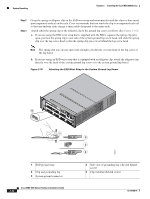
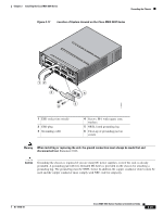
Starting Up the Switch Chapter 2 Installing the Cisco MDS 9200 Series To attach the grounding lug and cable to the chassis, follow these steps: Step 1 Step 2 Step 3 Step 4 Step 5 Step 6 Step 7 Use a wire-stripping tool to remove approximately 0.75 in. (19 mm) of the covering from the end of the grounding cable. Insert the stripped end of the grounding cable into the open end of the grounding lug. Use the crimping tool to secure the grounding cable in the grounding lug. Remove the adhesive label from the grounding pad on the chassis. Place the grounding lug against the grounding pad so that there is solid metal-to-metal contact, and insert the two M4 screws with washers through the holes in the grounding lug and into the grounding pad. Ensure that the lug and cable do not interfere with other equipment. Prepare the other end of the grounding cable and connect it to an appropriate grounding point in your site to ensure adequate earth ground. Starting Up the Switch This section provides instructions for powering up the switch and verifying component installation. Warning Hazardous voltage or energy is present on the backplane when the system is operating. Use caution when servicing. Statement 1034 Warning Blank faceplates and cover panels serve three important functions: they prevent exposure to hazardous voltages and currents inside the chassis; they contain electromagnetic interference (EMI) that might disrupt other equipment; and they direct the flow of cooling air through the chassis. Do not operate the system unless all cards, faceplates, front covers, and rear covers are in place. During this procedure, wear grounding wrist straps to avoid ESD damage to the switch. Statement 1029 Note Do not connect the MGMT 10/100 Ethernet port to the LAN until the initial switch configuration has been performed. For instructions on configuring the switch, see the Cisco MDS 9000 Family CLI Configuration Guide or the Cisco MDS 9000 Family Fabric Manager Configuration Guide. For instructions on connecting to the console port, see the "Connecting to the Console Port" section on page 3-2. Warning When installing or replacing the unit, the ground connection must always be made first and disconnected last. Statement 1046 To power up the switch and verify hardware operation, follow these steps: Step 1 Verify that empty module slots have filler panels installed, the faceplates of all modules are flush with the front of the chassis, the ejector levers are fully closed and approximately parallel to the front of the module, and the captive screws of the power supplies, fan module, and all supervisor, switching, or services modules are tight. 2-26 Cisco MDS 9200 Series Hardware Installation Guide OL-16188-01
-
 1
1 -
2
-
3
-
4
-
5
-
6
-
7
-
8
-
9
-
10
-
11
-
12
-
13
-
14
-
15
-
16
-
17
-
18
-
19
-
20
-
21
-
22
-
23
-
24
-
25
-
26
-
27
-
28
-
29
-
30
-
31
-
32
-
33
-
34
-
35
-
36
-
37
-
38
-
39
-
40
-
41
-
42
-
43
-
44
-
45
-
46
-
47
-
48
-
49
-
50
-
51
-
52
-
53
-
54
-
55
-
56
-
57
-
58
-
59
-
60
-
61
-
62
-
63
-
64
-
65
-
66
-
67
-
68
-
69
-
70
-
71
-
72
-
73
-
74
-
75
-
76
-
 77
77 -
 78
78 -
 79
79 -
 80
80 -
 81
81 -
 82
82 -
 83
83 -
 84
84 -
 85
85 -
 86
86 -
 87
87 -
88
-
89
-
90
-
91
-
92
-
93
-
94
-
95
-
96
-
97
-
98
-
99
-
100
-
101
-
102
-
103
-
104
-
105
-
106
-
107
-
108
-
109
-
110
-
111
-
112
-
113
-
114
-
115
-
116
-
117
-
118
-
119
-
120
-
121
-
122
-
123
-
124
-
125
-
126
-
127
-
128
-
129
-
130
-
131
-
132
-
133
-
134
-
135
-
136
-
137
-
138
-
139
-
140
-
141
-
142
-
143
-
144
-
145
-
146
-
147
-
148
-
149
-
150
-
151
-
152
-
153
-
154
-
155
-
156
-
157
-
158
-
159
-
160
-
161
-
162
-
163
-
164
 |
 |
