HP Color LaserJet CM1312 Service Manual
HP Color LaserJet CM1312 - Multifunction Printer Manual
 |
View all HP Color LaserJet CM1312 manuals
Add to My Manuals
Save this manual to your list of manuals |
HP Color LaserJet CM1312 manual content summary:
- HP Color LaserJet CM1312 | Service Manual - Page 1
HP Color LaserJet CM1312 MFP Series Service Manual - HP Color LaserJet CM1312 | Service Manual - Page 2
- HP Color LaserJet CM1312 | Service Manual - Page 3
HP Color LaserJet CM1312 MFP Series Service Manual - HP Color LaserJet CM1312 | Service Manual - Page 4
to change without notice. The only warranties for HP products and services are set forth in the express warranty statements accompanying such products and services. Nothing herein should be construed as constituting an additional warranty. HP shall not be liable for technical or editorial errors - HP Color LaserJet CM1312 | Service Manual - Page 5
10 Software for Macintosh 10 Embedded Web server 10 Supported printer drivers 11 Supported printer drivers for Windows 11 HP Universal Print Driver (UPD 11 UPD installation modes 11 Supported printer drivers for Macintosh 11 Software for other operating systems 12 System requirements - HP Color LaserJet CM1312 | Service Manual - Page 6
print media ...36 Supported paper types and tray capacity 37 Load paper and print media ...38 Load Tray 1 ...38 Load originals for copying, scanning, or faxing 39 Configure tray ...41 4 Manage and maintain the product Information pages ...44 HP ToolboxFX ...46 View the HP ToolboxFX ...46 Status - HP Color LaserJet CM1312 | Service Manual - Page 7
59 Check supplies status by using HP ToolboxFX 59 Store supplies 60 HP policy on non-HP supplies 60 HP fraud hotline 60 Recycle supplies 60 the exterior 70 Firmware updates ...70 Recover from a corrupted firmware download 70 5 Theory of operation Basic operation ...74 Major product systems - HP Color LaserJet CM1312 | Service Manual - Page 8
security features 98 PSTN operation ...98 Receive faxes when you hear fax tones 98 Distinctive ring function ...99 Fax by using Voice over IP services 99 The fax subsystem ...100 Fax card in the fax subsystem 100 Safety isolation 100 Safety-protection circuitry 100 Data path ...101 Hook state - HP Color LaserJet CM1312 | Service Manual - Page 9
107 Types of screws ...107 Service approach ...108 Before performing service 108 After performing service 108 Post-service tests ...109 Test 1 ( assembly 119 Separation roller (product base 120 Transfer roller ...122 Paper-guide assembly ...124 External panels, covers, and doors 125 Front door - HP Color LaserJet CM1312 | Service Manual - Page 10
the power supply (low voltage 179 Power supply (fuser) ...180 Fuser ...183 7 Problem solve Menu map ...188 Troubleshooting process ...189 Pre-troubleshooting checklist 189 Power-on checks ...190 Troubleshooting tools ...191 LED diagnostics ...191 Network LEDs (network models only 191 Control - HP Color LaserJet CM1312 | Service Manual - Page 11
-quality troubleshooting tools 205 Repetitive image defects 205 Calibrate the product 205 Internal print quality test pages 206 Cleaning page 206 Service page 206 Diagnostics pages 206 HP ToolboxFX software 208 Control-panel messages ...209 Event-log messages ...217 Paper-handling problems - HP Color LaserJet CM1312 | Service Manual - Page 12
248 Change the fax speed 249 Problems sending faxes 249 Problems receiving faxes 251 Performance problems ...254 Memory card problems (fax/memory-card models only Appendix A Service and support Hewlett-Packard limited warranty statement 293 Customer self repair warranty service 294 Print - HP Color LaserJet CM1312 | Service Manual - Page 13
Telephone Consumer Protection Act (United States 305 IC CS-03 requirements ...305 Declarations of conformity ...306 HP Color LaserJet CM1312 306 HP Color LaserJet CM1312nfi 306 Certificate of volatility ...308 Country/region specific statements 309 Laser safety ...309 Canadian DOC regulations - HP Color LaserJet CM1312 | Service Manual - Page 14
xii ENWW - HP Color LaserJet CM1312 | Service Manual - Page 15
1 Product basics ● Quick access to product information ● Product comparison ● Product features ● Product walkaround ● Supported operating systems ● Supported product software ● System requirements ● Connectivity ENWW 1 - HP Color LaserJet CM1312 | Service Manual - Page 16
/support/CM1312series Table 1-1 Product guides Guide Description HP Color LaserJet CM1312 MFP Provides step-by-step instructions for installing and setting up the product. Series Getting Started Guide HP Color LaserJet CM1312 MFP Provides detailed information for using the product and problem - HP Color LaserJet CM1312 | Service Manual - Page 17
configurations. Base models Fax/memory-card models ● Prints color print jobs at speeds up to 8 pages per minute Base model features, plus: (ppm) and monochrome print jobs at speeds up to 12 ppm. ● 10/100 Base-T network port. ● PCL 6 printer driver. ● V.34 fax and 8-megabyte (MB) flash fax - HP Color LaserJet CM1312 | Service Manual - Page 18
slots (fax/ ● memory-card models only) Networking (network ● models only) Printer driver features ● Interface connections ● ● ● Economical printing ● Supplies ● ● ● ● Accessibility ● ● ● Prints up to 8 ppm (color) or 12 ppm (monochrome). 1,200 dots per inch (dpi) with Image - HP Color LaserJet CM1312 | Service Manual - Page 19
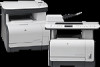
Product walkaround Base model front view 1 Tray 1 2 Print-cartridge door latch 3 Top (face-down) output bin 4 Flatbed scanner 5 Control panel 6 Front door for jam access ENWW Product walkaround 5 - HP Color LaserJet CM1312 | Service Manual - Page 20
Base model back view 7 Power connector 8 Rear door for jam access 9 Hi-Speed USB 2.0 port Fax/memory-card model front view 1 Tray 1 2 Print-cartridge door latch 3 Top (face-down) output bin 4 Control panel 5 Automatic document feeder (ADF) input tray 6 Automatic document feeder (ADF) output bin 7 - HP Color LaserJet CM1312 | Service Manual - Page 21
Fax/memory-card model back view 8 Power connector 9 Rear door for jam access 10 Fax ports 11 Hi-Speed USB 2.0 port and network port. Interface ports 1 Fax ports (fax/memory-card models only) 2 Network port (network models only) 3 Hi-Speed USB 2.0 port ENWW Product walkaround 7 - HP Color LaserJet CM1312 | Service Manual - Page 22
2003 Server (32-bit and 64-bit) NOTE: The PCL 5 UPD and HP postscript level 3 emulation drivers are available only on the HP support website: www.hp.com/support/CM1312series. Supported operating systems for Macintosh The device supports the following Macintosh operating systems: ● Mac OS X v10 - HP Color LaserJet CM1312 | Service Manual - Page 23
a browser-based management tool for HP Jetdirect-connected printers within your intranet, and it should be installed only on the network administrator's computer. To download a current version of HP Web Jetadmin and for the latest list of supported host systems, visit www.hp.com/go/webjetadmin. When - HP Color LaserJet CM1312 | Service Manual - Page 24
documentation ● Gain access to troubleshooting and maintenance tools ● Use HP Proactive Support to routinely scan your printing system and to prevent potential problems. HP Proactive Support can update software, firmware, and HP printer drivers. You can view HP ToolboxFX software when the product - HP Color LaserJet CM1312 | Service Manual - Page 25
Supported printer drivers Supported printer drivers for Windows ● PCL 5 UPD ● PCL 6 ● HP postscript level 3 UPD The printer drivers include online Help that has instructions for common printing tasks and also describes the buttons, checkboxes, and drop-down lists that are in the printer driver. - HP Color LaserJet CM1312 | Service Manual - Page 26
Software for other operating systems OS UNIX Linux Software For HP-UX and Solaris networks, go to www.hp.com/support/net_printing to download the HP Jetdirect printer installer for UNIX. For information, go to www.hp.com/go/linuxprinting. 12 Chapter 1 Product basics ENWW - HP Color LaserJet CM1312 | Service Manual - Page 27
● SVGA 800 x 600 monitor ● SVGA 800 x 600 monitor with 16-bit color (print driver, ● USB port with 16-bit color ● Internet Explorer 6.0 or higher (full installation) scan driver only) ● CD-ROM drive ● Internet Explorer 6.0 or ● USB port higher (full installation) ● USB port ● Safari - HP Color LaserJet CM1312 | Service Manual - Page 28
tables list the networking services/protocols that are supported on the product. Table 1-2 Printing Service name Description port9100 (Direct Mode) Printing service Line printer daemon (LPD) Printing service Table 1-3 Network product discovery Service name SLP (Service Location Protocol) mDNS - HP Color LaserJet CM1312 | Service Manual - Page 29
Table 1-5 IP addressing (continued) Service name BOOTP (bootstrap protocol) Auto IP Description For Automatic IP address assignment. IP address assignment. If neither a DHCP server nor a BOOTP server is present, this service allows the product to generate a unique IP address. ENWW Connectivity 15 - HP Color LaserJet CM1312 | Service Manual - Page 30
16 Chapter 1 Product basics ENWW - HP Color LaserJet CM1312 | Service Manual - Page 31
2 Control panel ● Control-panel walkaround ● Control-panel menus ENWW 17 - HP Color LaserJet CM1312 | Service Manual - Page 32
perform a copy operation in black and white. 6 Lighter/Darker button: change the lightness or darkness of the scanned image. 7 Copy Color button: perform a copy operation in color. 8 # Copies button: specify the number of copies. 9 Back button : go back to the previous menu 10 Setup button : access - HP Color LaserJet CM1312 | Service Manual - Page 33
panel .. ? 1 Speed dials. 4 speed dial buttons and one shift button to support up to 8 speed dials. 2 Fax Menu button. Access the Copy Black button. Perform a black and white copy operation. Start Copy Color button. Perform a color copy operation. 6 Scan Menu button. Access the scan menu. Start - HP Color LaserJet CM1312 | Service Manual - Page 34
from a memory card. ● Use the System setup menu to establish basic product settings such as language, print quality, or volume levels. ● Use the Service menu to restore default settings, clean the product, and activate special modes that affect print output. ● Use the Network configuration menu to - HP Color LaserJet CM1312 | Service Manual - Page 35
reduce or enlarge a copied document. Sets the default draft mode option. Sets the default multi-page flatbed copy option. Enables or disables the color copy button. The default light/dark setting for copies. The default contrast setting for copies. The default sharpen setting for copies. The default - HP Color LaserJet CM1312 | Service Manual - Page 36
out information about the color toner usage. Service page Prints out diagnostic information about paper type settings, copy quality settings, and other status settings. Diagnostics page Prints two pages with calibration and color patches for print-quality troubleshooting. Table 2-3 Photo setup - HP Color LaserJet CM1312 | Service Manual - Page 37
ring is generated to alert the user of an incoming voice call. ● Manual : The user must press the Start Fax button or use an extension phone each with a different ring pattern (on a phone system with distinctive-ring service). Double ● Triple ● Double and Triple All Rings: The product answers - HP Color LaserJet CM1312 | Service Manual - Page 38
Table 2-4 Fax setup menu (fax models only) (continued) Menu Item Sub-menu item Sub-menu item Description Advanced setup Def. Resolution Standard Fine Superfine Photo Sets the resolution for sent documents. Higher resolution images have more dots per inch (dpi), so they show more detail. Lower - HP Color LaserJet CM1312 | Service Manual - Page 39
Table 2-4 Fax setup menu (fax models only) (continued) Menu Item Sub-menu item Sub-menu item Description Advanced setup Detect dial tone On Off Sets whether the product should check for a dial tone before sending a fax. Billing codes On Off Enables the use of billing codes when set to On. A - HP Color LaserJet CM1312 | Service Manual - Page 40
percentage at which the control panel generates a low-toner message. Sets how the product reacts when it product should react when it detects that a color cartridge is empty. Select Stop printing to stop mode. Print out a tray-specific sheet of instructions and a test page with a border that can - HP Color LaserJet CM1312 | Service Manual - Page 41
indicating the results. Prints or schedules a report that is used to troubleshoot fax transmission issues. The error correction mode allows the sending device to it detects an error signal. The default setting is on. The fax service log prints out the last 40 entries in the fax log. Cleans - HP Color LaserJet CM1312 | Service Manual - Page 42
Table 2-6 Service menu (continued) Description on printed output. The cleaning process removes dust and excess toner from the paper path. When selected, the product prompts you to load IP settings via DHCP, BootP or AutoIP. Manual requires you to manually configure the IP address, subnet mask, and - HP Color LaserJet CM1312 | Service Manual - Page 43
before moving to the next one. After all three addresses connected to a computer. Network services IPv4 Sets whether the product will ) Sets the link speed manually if needed. 10T Full Photo Menu buttons respectively. These are the features supported by the function-specific menus. ● Use the - HP Color LaserJet CM1312 | Service Manual - Page 44
Table 2-8 Fax Menu (appears only if a memory card is in one of the memory-card slots) Menu item Sub-menu item Sub-menu item Description Send Send a fax Send a fax. On screen prompts guide the process. Redial Redial the last fax number and resend. Send fax later Allows a fax to be sent at - HP Color LaserJet CM1312 | Service Manual - Page 45
is in one of the memory-card slots) (continued) Menu item Sub-menu item Sub-menu item Description Phone Book Select an entry Individual Setup Group setup Select an individual or group dial entry for faxing. Edits the fax phone book speed dials and group-dial entries. The product supports up - HP Color LaserJet CM1312 | Service Manual - Page 46
Table 2-8 Fax Menu (appears only if a memory card is in one of the memory-card slots) (continued) Menu item Sub-menu item Sub-menu item Description Fax Reports Fax Confirmation Never Every fax Send fax only - HP Color LaserJet CM1312 | Service Manual - Page 47
images are printed at full size. Adjust the default photo settings for image size, paper size, paper type, number of copies, and output color (color or black & white). Rotate a photo stored on a memory card. View a slideshow of the photos on a memory card. Description Specify the number of copies - HP Color LaserJet CM1312 | Service Manual - Page 48
Light/Dark Options Optimize Copy Paper Multi-Page Copy Copy Collation Copy Draft Image Adjustment Sub-menu item Lightness Contrast Sharpen Background Color Balance Grayness Description Specify the contrast of the copy. Select settings to optimize the copy print quality. Specify the paper type - HP Color LaserJet CM1312 | Service Manual - Page 49
3 Paper and print media ● Supported paper and print media ● Supported paper types and tray capacity ● Load paper and print media ● Configure tray ENWW 35 - HP Color LaserJet CM1312 | Service Manual - Page 50
it adapts to various media. NOTE: To obtain best print results, select the appropriate paper size and type in the print driver before printing. Table 3-1 Supported paper and print media sizes Size Dimensions Tray 1 Letter 216 x 279 mm (8.5 x 11 inches) Legal 216 x 356 mm (8.5 x 14 inches - HP Color LaserJet CM1312 | Service Manual - Page 51
Supported paper types and tray capacity Media type Dimensions1 Weight Capacity2 Paper orientation Paper, including the following types: ● Plain ● Letterhead ● Color 1 The product supports a wide range of standard and custom sizes of print media. Check the printer driver for supported sizes. 2 - HP Color LaserJet CM1312 | Service Manual - Page 52
product and that the print is not skewed. Tray 1 has side and rear media guides. When loading media, adjust the media guides to match the length and width of the media that you are using. NOTE: sheets of media from feeding through the product at one time. 38 Chapter 3 Paper and print media ENWW - HP Color LaserJet CM1312 | Service Manual - Page 53
copied on top of the stack. If the media is longer than letter- or A4-sized paper, pull out the ADF input tray extension to support the media. 2. Slide the stack with printed side up into the ADF until it does not move any farther. Document loaded appears on the control - HP Color LaserJet CM1312 | Service Manual - Page 54
3. Adjust the media guides until they are snug against the media without restricting movement. Flatbed scanner NOTE: The maximum media size for flatbed scanning is letter/A4. For media - HP Color LaserJet CM1312 | Service Manual - Page 55
Configure tray When using Tray 1 for a specific size of paper, you can set the default size for the tray in HP ToolboxFX or from the control panel. In HP ToolboxFX, select Paper handling, and then select the size for the tray. To set the default paper size or type from the control panel - HP Color LaserJet CM1312 | Service Manual - Page 56
42 Chapter 3 Paper and print media ENWW - HP Color LaserJet CM1312 | Service Manual - Page 57
4 Manage and maintain the product ● Information pages ● HP ToolboxFX ● Embedded Web server ● Use HP Web Jetadmin software ● Security features ● Manage supplies ENWW 43 - HP Color LaserJet CM1312 | Service Manual - Page 58
problems with the product. NOTE: If the product language was not correctly set during installation, you can set the language manually so the information pages print in one of the supported and then press OK. PCL, PCL 6, or PS font list HP ToolboxFX, the embedded Web server, or HP Web Jetadmin. See HP - HP Color LaserJet CM1312 | Service Manual - Page 59
Page description Menu structure Shows the control-panel menus. Network report Shows the product network settings. Fax reports (fax models only) How to print the page 1. On the product control panel, press Setup . 2. Use the arrow buttons to select Reports, and then press OK. 3. Use the arrow - HP Color LaserJet CM1312 | Service Manual - Page 60
and Vista), click HP, click HP Color LaserJet CM1312 MFP Series, and then click HP ToolboxFX. Status The Status folder contains links to the following main pages: ● Device status. This page indicates product conditions such as a jam or an empty tray. After you correct a problem, click Refresh status - HP Color LaserJet CM1312 | Service Manual - Page 61
certain events occur. Events that trigger alerts include jams, low levels of toner in HP print cartridges, non-HP print cartridge in use, empty input trays, and specific error messages. Select pages that show the color print quality potential and overall print characteristics of the product. ENWW - HP Color LaserJet CM1312 | Service Manual - Page 62
Fax Use the HP ToolboxFX Fax tab to perform fax tasks from your computer. The machine. For more information about fax tasks, see the user guide. NOTE: You must click Apply before the changes take effect. Fax phone book Use the HP ToolboxFX fax phone book to add and remove individuals or groups - HP Color LaserJet CM1312 | Service Manual - Page 63
are valid characters for fax numbers R ●W space> NOTE: You must click Apply before the changes take effect. For more information about faxes, see the user guide. ENWW HP ToolboxFX 49 - HP Color LaserJet CM1312 | Service Manual - Page 64
. Use the HP Basic Color Match to adjust spot colors in your printed output. ● Animated demonstrations. View animated demonstrations for common troubleshooting procedures. ● User Guide. View information about the product usage, warranty, specifications, and support. The User Guide is available in - HP Color LaserJet CM1312 | Service Manual - Page 65
level that causes a Low toner pop-up alert. ● Service. Gain access to various procedures required to maintain the product. ● Device Polling. Change the product polling settings, which determine how often HP ToolboxFX collects data from the product. ● Save/Restore Settings. Save the current settings - HP Color LaserJet CM1312 | Service Manual - Page 66
on 100 x 150 mm (4 x 6 in) HP Color Laser Photo Paper. ● Calibrate Now. Set the product to calibrate immediately. NOTE: You must click Apply before your changes take effect. Print Density Use these settings to make fine adjustments in the amount of each color of toner that is used for your printed - HP Color LaserJet CM1312 | Service Manual - Page 67
does not affect highlight or midtone colors. Paper Types Use these options to configure print modes that correspond to the various media types. To reset all modes to factory default settings, select Restore modes. NOTE: You must click Apply before your changes take effect. ENWW HP ToolboxFX 53 - HP Color LaserJet CM1312 | Service Manual - Page 68
click Apply before the changes take effect. Service During the printing process, paper, toner and dust particles can accumulate inside the product. Over time, this buildup can cause print-quality problems such as toner specks or smearing. The HP ToolboxFX provides an easy method for cleaning the - HP Color LaserJet CM1312 | Service Manual - Page 69
PCL5 Use these options to configure the settings when you are using the PCL print personality. NOTE: You must click Apply before your changes take effect. PostScript Use this option when the network-related settings for the product when it is connected to an IP-based network. ENWW HP ToolboxFX 55 - HP Color LaserJet CM1312 | Service Manual - Page 70
server resides on a hardware device (such as an HP LaserJet product) or in firmware, rather than as software install or configure, but you must have a supported Web browser on the computer. To gain access remaining life on all supplies and order new ones ● View and change part of the product - HP Color LaserJet CM1312 | Service Manual - Page 71
troubleshooting network-connected peripherals. The intuitive browser interface simplifies cross-platform management of a wide range of devices, including HP and non-HP devices. Management is proactive, allowing network administrators the ability to resolve issues before users are affected. Download - HP Color LaserJet CM1312 | Service Manual - Page 72
Turn on private receive feature The password-protection feature must be turned on before the private-receive feature can be activated. 1. On the control panel, press Setup . 2. Use the arrow buttons to select Fax setup, and then press OK. 3. Use the arrow buttons to select Advanced setup, and then - HP Color LaserJet CM1312 | Service Manual - Page 73
when a print cartridge is low. If the product is directly connected to a computer, you can set HP ToolboxFX to notify you when supplies are low. Check supplies status by using the control panel Do one of the following: ● Check the product control panel, which indicates when a print cartridge is low - HP Color LaserJet CM1312 | Service Manual - Page 74
interpreter is a service that will translate between you and the representative for the HP fraud hotline. Recycle supplies To install a new HP print cartridge, follow the instructions that are included in the box that contains the new supply, or see the getting started guide. To recycle supplies - HP Color LaserJet CM1312 | Service Manual - Page 75
Replace supplies Print cartridge 1 Cartridge E-label 2 Plastic shield 3 Imaging Drum. Do not touch the imaging drum on the bottom of the print cartridge. Fingerprints on the imaging drum can cause print-quality problems. 1. Open the front door. ENWW Manage supplies 61 - HP Color LaserJet CM1312 | Service Manual - Page 76
2. Pull out the print-cartridge drawer. 3. Grasp the handle on the old print cartridge and then pull the cartridge straight up to remove it. 4. Remove the new print cartridge from the packaging. 62 Chapter 4 Manage and maintain the product ENWW - HP Color LaserJet CM1312 | Service Manual - Page 77
cartridge. CAUTION: Do not touch the imaging drum on the bottom of the print cartridge. Fingerprints on the imaging drum can cause print-quality problems. 6. Insert the new print cartridge into the product. 7. Pull the tab on the left side of the print cartridge straight up to completely remove - HP Color LaserJet CM1312 | Service Manual - Page 78
the box for the new print cartridge. Follow the recycling instructions that are included in the box. CAUTION: If toner gets on any clothing, wipe it off with a , toner, and dust particles can accumulate inside the product. Over time, this buildup can cause print-quality problems such as toner specks - HP Color LaserJet CM1312 | Service Manual - Page 79
that the product is turned on and in the Ready state, and that media is loaded in Tray 1. 2. Open HP ToolboxFX, click the product, and then click the System Settings tab. 3. Click the Service tab, and then click Start. A page feeds through the product slowly. Discard the page when the process is - HP Color LaserJet CM1312 | Service Manual - Page 80
Clean the automatic document feeder (ADF) pickup roller assembly If the ADF has trouble feeding documents, clean the ADF pickup roller assembly. 1. Turn off the product and unplug the power cord. 2. Open the ADF cover. 66 Chapter 4 Manage and maintain the product ENWW - HP Color LaserJet CM1312 | Service Manual - Page 81
until the assembly is clean. 4. Lower the green lever assembly and close the ADF cover. NOTE: If you are experiencing jams in the ADF, contact HP. See www.hp.com/support/ CM1312series or the support flyer that came in the product box. ENWW Manage supplies 67 - HP Color LaserJet CM1312 | Service Manual - Page 82
5. Plug in the product, and then turn on the product. Clean the lid backing Minor debris can accumulate on the white document lid backing that is located underneath the product lid. 1. Turn off the product, unplug the power cord, and raise the lid. 2. Clean the white document lid backing by using a - HP Color LaserJet CM1312 | Service Manual - Page 83
CAUTION: Do not use paper-based wipes because they might scratch the backing. 5. If this does not clean the backing well enough, repeat the previous steps and use isopropyl alcohol to dampen the cloth or sponge, and then wipe the backing thoroughly with a damp cloth to remove any residual alcohol. - HP Color LaserJet CM1312 | Service Manual - Page 84
updates Firmware updates and installation instructions for this product are available at www.hp.com/support/ CM1312series. Click Downloads and drivers, click the operating system, and then select the firmware download for the product. NOTE: Interrupting the firmware download can cause the product to - HP Color LaserJet CM1312 | Service Manual - Page 85
on the product, and then wait for the message ready 2 Download to appear. 4. On the computer, cancel any alerts about a new device being connected. 5. On the computer, open the Printers and Faxes control panel. 6. Right-click the printer driver for the product model that is being updated, and then - HP Color LaserJet CM1312 | Service Manual - Page 86
. If the product was network-connected, disconnect the USB cable, and then reconnect the product to the network cable. NOTE: In rare instances, the print driver software might need to be uninstalled and reinstalled. 72 Chapter 4 Manage and maintain the product ENWW - HP Color LaserJet CM1312 | Service Manual - Page 87
5 Theory of operation This chapter presents an overview of the major components of the product, and includes a detailed discussion of the image-formation system. ● Basic operation ● Engine control system ● Laser/scanner system ● Image-formation system ● Pickup-and-feed system ● Scanner system (base - HP Color LaserJet CM1312 | Service Manual - Page 88
Basic operation Major product systems The product includes the following systems: ● Engine control system ● Laser/scanner system ● Image-formation system ● Pickup-and-feed system Figure 5-1 Product systems LASER/SCANNER SYSTEM ENGINE CONTROL SYSTEM IMAGE-FORMA TION SYSTEM PICKUP-AND-FEED SYSTEM - HP Color LaserJet CM1312 | Service Manual - Page 89
closed until the drum-phase adjustment is complete Clears the potential from the drum surface, adjusts the drum phase, and cleans the ETB Detects the toner level, cartridge presence, and environment; completes any required calibration (color ENWW Basic operation 75 - HP Color LaserJet CM1312 | Service Manual - Page 90
mode when the formatter sends a sleep command, and performs color registration and the image stability control when the formatter sends those of paper Forms the images on the photosensitive drum and transfers the toner image to the print media Performs image stabilization at a specified print - HP Color LaserJet CM1312 | Service Manual - Page 91
Engine control system The engine control system coordinates all product functions and drives the other three systems. The engine control system contains the DC controller, high-voltage power supply PCA, and low-voltage power supply/fuser power supply unit. Figure 5-3 Engine control system components - HP Color LaserJet CM1312 | Service Manual - Page 92
DC controller The DC controller controls the product operational sequence. Figure 5-4 DC controller circuit diagram Fuser unit DC controller AC input Cartridge Fuser power supply Low-voltage power supply High-voltage power supply Formatter M Motor Solenoid Switch Sensor Sensor ITB unit Laser - HP Color LaserJet CM1312 | Service Manual - Page 93
Low-voltage power supply The low-voltage power supply and the fuser power supply convert AC power from the power receptacle into DC power to cover the DC loads. Figure 5-5 Low-voltage power supply AC input Fuse FU901 Noise filter Power switch SW801 Fuse FU801 Fuser control circuit Fuser power - HP Color LaserJet CM1312 | Service Manual - Page 94
High-voltage power supply The DC controller controls the high-voltage power supply to generate high-voltage biases. The highvoltage power supply generates the high-voltage biases that are applied to the primary charging roller, developing roller, primary transfer pad, secondary transfer roller, and - HP Color LaserJet CM1312 | Service Manual - Page 95
Laser/scanner system The formatter sends video signals to the DC controller, which controls the laser/scanner. When the laser/ scanner system receives those signals, it converts them to latent images on the photosensitive drum. Figure 5-7 Laser/scanner system Laser failure detection The optical - HP Color LaserJet CM1312 | Service Manual - Page 96
on media. The product includes four print cartridges that contain the toner that is used to create the image on the media. Toner is applied in the following order, using only the colors necessary for a specific image: yellow (Y), magenta (M), cyan (C), and black (Bk). Figure 5-8 Image-formation - HP Color LaserJet CM1312 | Service Manual - Page 97
These processes are divided into nine steps, which are shown in Figure 5-9 Image-formation process on page 83 and described in the following sections. Figure 5-9 Image-formation process Delivery 7. Fusing Fuser Latent image formation 2. Laser beam exposure 1. Primary charging 3. Development - HP Color LaserJet CM1312 | Service Manual - Page 98
Exposed area Developing stage The developing cylinder comes in contact with the photosensitive drum and deposits toner on the electrostatic latent image. Step 3: development Toner acquires a negative charge as a result of the friction from the developing cylinder rotating against the developing - HP Color LaserJet CM1312 | Service Manual - Page 99
transfers to the ITB from the drum surface. Figure 5-13 Primary transfer Photosensitive drum Primary transfer pad ITB DC bias Step 5: secondary transfer The toner image on the ITB is transferred to the print media. The DC positive bias is applied to the secondary transfer roller. As the media - HP Color LaserJet CM1312 | Service Manual - Page 100
ITB drive roller Secondary transfer roller Fusing stage Until the fusing stage is complete, the image is not permanently affixed to the print media. The toner can be easily smudged until the heat and pressure of the fusing process fix the image to the sheet. Step 7: fusing The product uses an - HP Color LaserJet CM1312 | Service Manual - Page 101
is reverse-transferred to the photosensitive drum from the ITB surface. Figure 5-17 ITB cleaning Positive potential waste toner Negative potential waste toner Cartridge Partition sheet ITB cleaning brush Sweeper strip DC bias Photosensitive drum ITB cleaning roller ITB DC bias ENWW Image - HP Color LaserJet CM1312 | Service Manual - Page 102
The cleaning blade scrapes the residual toner off the surface of the photosensitive drum and deposits it in the waste-toner container. The drum is now detects the signal from the developing homeposition sensor. All four color developing rollers disengage from the photosensitive drums when the product - HP Color LaserJet CM1312 | Service Manual - Page 103
Pickup-and-feed system The pickup-and-feed system picks up and feeds the print media. It consists of several types of feed rollers. Figure 5-19 Pickup-and-feed system SR609 M703 M701 SR603 SR602 M702 SL705 SR601 Number M701 M702 M703 SL705 Description Main motor Pickup motor Fuser motor - HP Color LaserJet CM1312 | Service Manual - Page 104
Jam detection The product uses the following sensors to detect the presence of media and to check whether media is being fed correctly or has jammed: ● Cassette media-presence sensor ● Top-of-page sensor ● Loop sensor ● Fuser delivery sensor The product detects the following jams: ● Pickup delay jam - HP Color LaserJet CM1312 | Service Manual - Page 105
in a single row of CCD sensors that cover the entire page width. Because only one color is captured for each line per exposure, the three colors are recombined electronically to create the full color image. For monochromatic scans or copies, all three LEDs are illuminated to create a white light - HP Color LaserJet CM1312 | Service Manual - Page 106
there is a special white calibration label. Calibration is the most important step in creating a high quality image. Calibration problems can include color inaccuracies, brightness inaccuracies, and vertical streaks through the image. The calibration process identifies any bad pixels and enables the - HP Color LaserJet CM1312 | Service Manual - Page 107
sections describe how the document scanner and the automatic document feeder (ADF) function. Scanner functions The scanner uses a light source, a color-separation method, and a charge-coupled device (CCD) array to collect optical information about the document and transform that into an image - HP Color LaserJet CM1312 | Service Manual - Page 108
distance from the ADF glass, detects the sheet. This alerts the scanner to start when the page reaches the glass. The scanner acquires the image, one raster line at a time, until it detects the end of the page. The page is then ejected. The pick and feed steps are repeated as - HP Color LaserJet CM1312 | Service Manual - Page 109
OUTPUT AREA The paper-present sensor determines if paper is in the ADF. The form sensor detects the top and bottom edges of the document. One other sensor detects an open ADF door. ENWW Scanner and ADF functions and operation (fax/memory-card models) 95 - HP Color LaserJet CM1312 | Service Manual - Page 110
ADF jam detection The ADF has two sensors that detect paper. The paper-present sensor detects the presence of media in the ADF input tray. The form sensor detects media moving through the ADF. If a jam is detected, the ADF immediately stops the paper feeding and a jam message appears on the control- - HP Color LaserJet CM1312 | Service Manual - Page 111
reader consists of slots where the following memory cards can be inserted: ● CompactFlash ● Memory Stick ● Memory Stick PRO ● Secure Digital ● MultiMediaCard ● xD Only one card can be installed at a time. The green memory card LED will blink when the product is reading the installed memory card. The - HP Color LaserJet CM1312 | Service Manual - Page 112
RING wires appear on pins 3 and 4 of the RJ-11 modular jack (the one on the fax card). These two wires do not have to be polarized because calls, and you hear fax tones when you answer the extension phone, receive the fax in one of two ways: ● If you are near the product, press Start Fax on the - HP Color LaserJet CM1312 | Service Manual - Page 113
-ring services that telephone companies provide in all countries/regions. HP does then press OK. 5. Use the arrow buttons to select one of the following options: NOTE: The control-panel display service supports fax over IP services. Because the installation process varies, the VoIP service - HP Color LaserJet CM1312 | Service Manual - Page 114
VoIP network. If you continue to have problems faxing, contact your VoIP provider. The fax . The fax subsystem is designed to support V.34 fax transmission, lower speeds (such fax card are used in the product. One is used in the North American, South low voltage. A series thermal switch works - HP Color LaserJet CM1312 | Service Manual - Page 115
the signal to ensure that the product does not go off-hook (and disconnect a downstream call) until it has been authorized to do so (by a manual fax start or the detection of the appropriate tones). Hook switch control In the silicon DAA the CODEC controls the hook switch directly. The CODEC - HP Color LaserJet CM1312 | Service Manual - Page 116
fax cable. To obtain a special fax cable, contact your local telephone service provider. Fax page storage in flash memory Fax pages are the electronic images Users can reprint faxes in case the print cartridge runs out of toner or the product experiences other errors while printing faxes. The product - HP Color LaserJet CM1312 | Service Manual - Page 117
the original document immediately after it is scanned, eliminating the need to wait until the fax is transmission is complete. Because fax pages are stored in flash memory rather than RAM, more RAM is available to handle larger and more complicated copy and print jobs. ENWW Fax functions and - HP Color LaserJet CM1312 | Service Manual - Page 118
104 Chapter 5 Theory of operation ENWW - HP Color LaserJet CM1312 | Service Manual - Page 119
6 Removal and replacement ● Removal and replacement strategy ● Service approach ● Print cartridges ● Control-panel overlay (base model) ● Control panel (base model) ● Control-panel bezel (fax/memory-card models) ● Control panel (fax/memory-card models) ● - HP Color LaserJet CM1312 | Service Manual - Page 120
HP does not support repairing individual subassemblies or problem solving at the component level. Note the length, diameter, color , lance points, or wire-harness guides. General cautions during removal and replacement removing product parts. Always perform service work at an ESD-protected workstation - HP Color LaserJet CM1312 | Service Manual - Page 121
screw for the correct shorter screw) can cause damage to the product or interfere with product operation. Do not intermix screws that are removed with one component with the screws that are removed from another component. For a complete list of screw types and part numbers, see Parts and diagrams on - HP Color LaserJet CM1312 | Service Manual - Page 122
approach Before performing service ● Remove all media from the product. ● Turn off the power using the power switch. ● Unplug the power cable and interface cable(s). ● Place the product on an ESD mat (if one is available). If an ESD workstation or mat is not available, ground yourself by touching - HP Color LaserJet CM1312 | Service Manual - Page 123
Post-service tests After service has been completed, perform the following tests to verify that the repair or replacement was successful. Test 1 (print-quality a valid fax number and send the fax job. 3. Verify that the send quality and receive quality meet expectations. ENWW Service approach 109 - HP Color LaserJet CM1312 | Service Manual - Page 124
bezel (fax/memory-card models) Control panel (fax/memory-card models) Pickup roller ADF pickup-roller assembly Separation roller Transfer roller Paper-guide assembly Front door and front-lower cover door Print-cartridge drawer Right cover Left cover Rear-upper cover Top Cover Power supply - HP Color LaserJet CM1312 | Service Manual - Page 125
dry cloth and wash the clothing in cold water. Hot water sets toner into the fabric. 1. Open the front door and pull out the print of the print cartridge. Finger prints on the imaging drum can cause print-quality problems. Do not allow the image drum to contact any surface when the cartridges are - HP Color LaserJet CM1312 | Service Manual - Page 126
Control-panel overlay (base model) TIP: It is not necessary to remove the original overlay to install a replacement overlay. However, installing more than three replacement overlays over the original might interfere with the operation of the control panel buttons. 1. Carefully peel the control-panel - HP Color LaserJet CM1312 | Service Manual - Page 127
ESD). Look for the ESD reminder when removing product parts. Always perform service work at an ESD-protected workstation or mat. If an ESD workstation See Control-panel overlay (base model) on page 112. 2. Remove one screw (callout 1). Figure 6-5 Remove the control-panel (1 of 3; base model) - HP Color LaserJet CM1312 | Service Manual - Page 128
, and then slide it towards the front of the product to release it. Figure 6-6 Remove the control-panel (2 of 3; base model) 4. Disconnect one FFC (callout 2) and then remove the control panel. Figure 6-7 Remove the control-panel (3 of 3; base model) 2 114 Chapter 6 Removal and replacement ENWW - HP Color LaserJet CM1312 | Service Manual - Page 129
Control-panel bezel (fax/memory-card models) Carefully pry up on one end of the control-panel bezel to release it. Continue to pry up on the bezel to remove it. Figure 6-8 Remove the control-panel bezel (fax/memory-card models) ENWW Control-panel bezel (fax/memory-card models) 115 - HP Color LaserJet CM1312 | Service Manual - Page 130
Control panel (fax/memory-card models) 1. Remove the control-panel bezel. See Control-panel bezel (fax/memory-card models) on page 115. 2. Release one tab (callout 1) and then slide the control panel toward the left side of the product to release it. Figure 6-9 Remove the control-panel (1 of 2; fax/ - HP Color LaserJet CM1312 | Service Manual - Page 131
2. When you reinstall the control panel, make sure the two lower tabs on the control panel (callout 3), and the three upper tabs on the control panel (callout 4) are positioned under the tabs on the scanner chassis (callout 5). Figure 6-11 Reinstall the control-panel (fax/memory-card models) 5 4 3 - HP Color LaserJet CM1312 | Service Manual - Page 132
main menus. d. Use the arrow buttons to highlight 2ndary Service, and then press OK. e. Use the arrow buttons to if the product is placed front-side up. Always support the ADF and scanner cover before placing the product problems. Figure 6-12 Remove the pickup roller 118 Chapter 6 Removal - HP Color LaserJet CM1312 | Service Manual - Page 133
ADF pickup roller assembly 1. Open the ADF cover. 2. Disconnect one spring (callout 1). Figure 6-13 Remove the ADF pickup roller assembly (1 of 2) 1 3. Lift up on the end of the assembly, and then slide it toward the - HP Color LaserJet CM1312 | Service Manual - Page 134
to replace the roller. Skin oils on the roller can cause paper pickup problems. 1. Remove paper tray (if installed), and then carefully place the product can open suddenly if the product is placed front-side up. Always support the ADF and scanner cover before placing the product frontside up. NOTE: - HP Color LaserJet CM1312 | Service Manual - Page 135
3. Release the roller holder to release the roller-locking pins. Remove the separation roller. Figure 6-16 Remove the separation roller (2 of 2) ENWW Paper-feed assemblies 121 - HP Color LaserJet CM1312 | Service Manual - Page 136
slot in the mounting bracket. Figure 6-17 Remove the transfer roller (1 of 3) 3. Remove the clip. Repeat these steps for the remaining retainer clip. TIP: One of the clips is made from a black conductive plastic. Make sure that the clips are reinstalled on the side of the transfer roller that they - HP Color LaserJet CM1312 | Service Manual - Page 137
4. Slide the roller to one side to disengage the roller shaft from the mounting bracket, and then remove the transfer roller. CAUTION: Do not touch the black sponge portion of the roller. Skin oils can cause print-quality problems. Figure 6-19 Remove the transfer roller (3 of 3) ENWW Paper-feed - HP Color LaserJet CM1312 | Service Manual - Page 138
Paper-guide assembly 1. Release one captive screw (callout 1) and release two tabs (callout 2). Figure 6-20 Remove the paper-guide assembly (1 of 2) 2 1 2. Remove the paper-guide assembly Figure 6-21 Remove the paper-guide assembly (2 of 2) 124 Chapter 6 Removal and replacement ENWW - HP Color LaserJet CM1312 | Service Manual - Page 139
door and pull out the print-cartridge drawer. Figure 6-22 Remove the front door and front-lower cover (1 of 13) 2. Use a small flatblade screw driver to release one tab (callout 1) on the cartridge-drawer stop. TIP: This clip slightly extends under the edge of the top cover. In the next step, you - HP Color LaserJet CM1312 | Service Manual - Page 140
3. Push in on the edge of the top cover, and then rotate the end of the drawer stop toward the center of the print-cartridge drawer. Figure 6-24 Remove the front door and front-lower cover (3 of 13) 1 2 4. Remove the drawer stop. Repeat the previous steps to remove the remaining drawer stop. Figure - HP Color LaserJet CM1312 | Service Manual - Page 141
captive and can open suddenly if the product is placed front-side up. Always support the ADF and scanner cover before placing the product frontside up. 7. Release three tabs (callout 3) and then push the guide (callout 4) into the product (away from the tray 1 cavity). Figure 6-27 Remove the front - HP Color LaserJet CM1312 | Service Manual - Page 142
8. Remove the guide through the front-door opening. Figure 6-28 Remove the front door and front-lower cover (7 of 13) 9. Carefully push the left-side front-lower door - HP Color LaserJet CM1312 | Service Manual - Page 143
hinge. Remove the front-lower door. Figure 6-30 Remove the front door and front-lower cover (9 of 13) 1 2 11. Use a small flatblade screwdriver to release one tab (callout 5) on the left-side front-door cam. Figure 6-31 Remove the front door and front-lower cover (10 of 13) 5 ENWW External panels - HP Color LaserJet CM1312 | Service Manual - Page 144
12. Slide the cam toward the center of the door to remove it. Repeat these steps for the right-side frontdoor cam. CAUTION: The hinge pin (callout 6) on the cam can be easily broken. You must apply even pressure on the cam to remove it without any twist motion that will break the hinge pin off of - HP Color LaserJet CM1312 | Service Manual - Page 145
14. Lower the left side of the door, and then slide it to the left to release the right-side door hinge pin. Remove the door. Figure 6-34 Remove the front door and front-lower cover (13 of 13) 1 2 ENWW External panels, covers, and doors 131 - HP Color LaserJet CM1312 | Service Manual - Page 146
Right cover 1. Remove one screw (callout 1). Figure 6-35 Remove the right cover (1 of 5) 1 2. Carefully pull the front of the right cover away from the product to release one tab. Figure 6-36 Remove the right cover (2 of 5) 132 Chapter 6 Removal and replacement ENWW - HP Color LaserJet CM1312 | Service Manual - Page 147
3. Use a small flatblade screwdriver to release one tab (callout 2). Figure 6-37 Remove the right cover (3 of 5) 2 4. Use a small flatblade screwdriver to release two tabs (callout 3). Figure 6-38 Remove the right cover (4 of 5) 3 ENWW External panels, covers, and doors 133 - HP Color LaserJet CM1312 | Service Manual - Page 148
5. Separate the cover away from the product to remove it. Figure 6-39 Remove the right cover (5 of 5) 134 Chapter 6 Removal and replacement ENWW - HP Color LaserJet CM1312 | Service Manual - Page 149
Left cover 1. Remove one screw (callout 1). Figure 6-40 Remove the left cover (1 of 4) 1 2. Open the front door, and then use a small flatblade screwdriver to release four tabs (callout 2). Figure 6-41 Remove the left cover (2 of 4) 2 ENWW External panels, covers, and doors 135 - HP Color LaserJet CM1312 | Service Manual - Page 150
3. Use a small flatblade screwdriver to release three tabs (callout 3) at the back of the product. Figure 6-42 Remove the left cover (3 of 4) 3 4. Separate the cover away from the product to remove it. Figure 6-43 Remove the left cover (4 of 4) 136 Chapter 6 Removal and replacement ENWW - HP Color LaserJet CM1312 | Service Manual - Page 151
1. Remove the right cover. See Right cover on page 132. 2. Fax/memory-card models only: Remove two screws (callout 1), and then disconnect one FFC (callout 2) Figure 6-44 Remove the front-right (1 of 3) 1 2 3. Use a small flatblade screwdriver to release two tabs (callout 3). Figure 6-45 Remove the - HP Color LaserJet CM1312 | Service Manual - Page 152
4. Remove the front-right cover. NOTE: The base model will not have the memory-card reader PCA installed as shown below. Figure 6-46 Remove the front-right cover (3 of 3) Reinstall the front-right cover Fax/memory-card models only: If you are installing a replacement front-right cover, remove the - HP Color LaserJet CM1312 | Service Manual - Page 153
only) 1. Remove the following components: ● Right cover. See Right cover on page 132. ● Front-right cover. See Front-right cover on page 137. 2. Release one tab (callout 1), and then rotate the memory-card reader PCA assembly away from the front-right cover. Figure 6-47 Remove the memory-card reader - HP Color LaserJet CM1312 | Service Manual - Page 154
page 137. ● Memory-card reader PCA (fax/memory-card models only). See Memory-card reader PCA (fax/memory-card models only) on page 139. 2. Release one tab (callout 1). Figure 6-49 Remove the card cover or blanking cover (1 of 2) 1 140 Chapter 6 Removal and replacement ENWW - HP Color LaserJet CM1312 | Service Manual - Page 155
3. Remove the card or blanking cover. Figure 6-50 Remove the card cover or blanking cover (2 of 2) ENWW External panels, covers, and doors 141 - HP Color LaserJet CM1312 | Service Manual - Page 156
Rear-side cover 1. Remove the right cover. See Right cover on page 132. 2. Open the rear door. 3. Use a small flatblade screwdriver to release two tabs (callout 1). Figure 6-51 Remove the rear-side cover (1 of 2) 1 4. Remove the rear-side cover. Figure 6-52 Remove the rear-side cover (2 of 2) 142 - HP Color LaserJet CM1312 | Service Manual - Page 157
Rear-upper cover 1. Remove the following components: ● Right cover. See Right cover on page 132. ● Left cover. See Left cover on page 135. ● Rear-side cover. See Rear-side cover on page 142. 2. Open the rear door. 3. Use a small flatblade screwdriver to release two tabs (callout 1). TIP: Push down - HP Color LaserJet CM1312 | Service Manual - Page 158
4. Rotate the bottom of the rear-upper cover away from the product to remove it. Figure 6-54 Remove the rear-upper cover (2 of 2) 144 Chapter 6 Removal and replacement ENWW - HP Color LaserJet CM1312 | Service Manual - Page 159
cover. See Rear-side cover on page 142. 2. Remove two screws (callout 1) Figure 6-55 Remove the rear door and rear-lower cover (1 of 4) 1 3. Release one pin (callout 2) and then slide the rear door and rear-lower cover towards the side of the product with the interface connectors. Figure 6-56 Remove - HP Color LaserJet CM1312 | Service Manual - Page 160
the rear door (callout 4). NOTE: If you are installing a replacement rear-lower door, remove the paper-guide assembly from the discarded door, and then install it on the replacement door. See Paper-guide assembly on page 124. Figure 6-58 Remove the rear door and rear-lower cover (4 of 4) 3 4 146 - HP Color LaserJet CM1312 | Service Manual - Page 161
Scanner assembly 1. Remove the right cover. See Right cover on page 132. 2. Disconnect one ground-wire lug (callout 1), two wire-harness connectors (callout 2; J4 and P1), and three FFCs (callout 3; J1, J2, and J3). Figure 6-59 Remove the scanner - HP Color LaserJet CM1312 | Service Manual - Page 162
4. Slightly lift up the back of the scanner, and then slide it toward the front of the product. Figure 6-61 Remove the scanner assembly (3 of 4) 5. Lift the scanner straight up and off of the product. Figure 6-62 Remove the scanner assembly (4 of 4) 148 Chapter 6 Removal and replacement ENWW - HP Color LaserJet CM1312 | Service Manual - Page 163
. ● Rear-upper cover. See Rear-upper cover on page 143. ● Scanner assembly. See Scanner assembly on page 147. 2. Remove four screws (callout 1) and then disconnect one wire-harness connector (callout 2, P2). Figure 6-63 Remove the top cover (1 of 3) 1 2 ENWW External panels, covers, and doors 149 - HP Color LaserJet CM1312 | Service Manual - Page 164
3. Remove three screws (callout 3) at the top-left side of the product. Figure 6-64 Remove the top cover (2 of 3) 3 4. Remove the top cover. Figure 6-65 Remove the top cover (3 of 3) 150 Chapter 6 Removal and replacement ENWW - HP Color LaserJet CM1312 | Service Manual - Page 165
Open the front door and out the print-cartridge drawer. Figure 6-66 Remove the print-cartridge drawer (1 of 5) 2. Use a small flatblade screw driver to release one tab (callout 1) on the cartridge-drawer stop. TIP: This clip slightly extends under the edge of the top cover (arrow). In the next step - HP Color LaserJet CM1312 | Service Manual - Page 166
3. Push in on the edge of the top cover, and then rotate the end of the drawer stop toward the center of the print-cartridge drawer. Figure 6-68 Remove the print-cartridge drawer (3 of 5) 1 2 4. Remove the drawer stop. Repeat the previous steps to remove the remaining drawer stop. Figure 6-69 Remove - HP Color LaserJet CM1312 | Service Manual - Page 167
5. Pull the print-cartridge drawer out of the product to remove it. Figure 6-70 Remove the print-cartridge drawer (5 of 5) ENWW Internal assemblies 153 - HP Color LaserJet CM1312 | Service Manual - Page 168
Main motor 1. Remove the right cover. See Right cover on page 132. 2. Disconnect one wire-harness connector (callout 1), and then release two tabs (callout 2) to release the black-plastic retainer (callout 3). Slide the retainer down and separate it from - HP Color LaserJet CM1312 | Service Manual - Page 169
: ● Right cover. See Right cover on page 132. ● Scanner assembly. See Scanner assembly on page 147. 2. Disconnect one wire-harness connector (callout 1; P2), and then remove one clip (callout 2). Figure 6-73 Remove the speaker (1 of 2) 2 1 3. Remove the speaker from the product. CAUTION: Do not - HP Color LaserJet CM1312 | Service Manual - Page 170
page 135. ● Rear-side cover. See Rear-side cover on page 142. ● Print-cartridge drawer. See Print-cartridge drawer on page 151. 2. Disconnect one wire-harness connector (callout 1), and then release the wire harness from the retainer (callout 2). Figure 6-75 Remove the ITB (1 of 5) 1 2 156 Chapter - HP Color LaserJet CM1312 | Service Manual - Page 171
3. Open the rear door, and then remove one screw (callout 3), and then remove the print-cartridge door stop (callout 4). Figure 6-76 Remove the ITB black plastic transfer belt. Skin oils on the belt might cause printquality problems. Figure 6-77 Remove the ITB (3 of 5) ENWW Internal assemblies 157 - HP Color LaserJet CM1312 | Service Manual - Page 172
5. Feed the ITB wire harness (callout 5) through an opening in the chassis (callout 6). Figure 6-78 Remove the ITB (4 of 5) 6 5 6. Carefully pull the ITB straight out of the product. WARNING! Handle the ITB by its hard plastic sides to avoid damage to the sheet metal frame. The lower sheet-metal - HP Color LaserJet CM1312 | Service Manual - Page 173
of the assembly. CAUTION: Avoid touching the black-plastic transfer belt or roller. Skin oils on the belt or roller might cause print-quality problems. ● Do not let the transfer belt contact hard or sharp objects. CAUTION: Scratches, punctures, or other damage to the belt will cause print-quality - HP Color LaserJet CM1312 | Service Manual - Page 174
the tape so that it makes contact or adheres to the transfer belt. Tape or tape residue on the transfer belt will cause print-quality problems. NOTE: Make sure that you remove all of the tape and tape residue after installing the ITB. Figure 6-81 Reinstall the ITB (2 of 2) 160 Chapter - HP Color LaserJet CM1312 | Service Manual - Page 175
the formatter at the same time will result in severe print-quality problems. Replacing the DC controller PCA before the formatter PCA Use the (ESD). Look for the ESD reminder when removing product parts. Always perform service work at an ESD-protected workstation or mat. If an ESD workstation or - HP Color LaserJet CM1312 | Service Manual - Page 176
(callout 1) from the guide (callout 2). TIP: It might be easier to remove the FFC from the guide, if you disconnect one end. Figure 6-82 Remove the DC controller PCA (1 of 6) 1 2 3. Release two tabs (callout 3) on the guide. Figure 6-83 Remove the DC controller PCA (2 of 6) 3 162 Chapter 6 Removal - HP Color LaserJet CM1312 | Service Manual - Page 177
4. Remove the guide. Figure 6-84 Remove the DC controller PCA (3 of 6) 5. Release two tabs (callout 4) and then remove the protective cover (callout 5). Figure 6-85 Remove the DC controller PCA (4 of 6) 4 5 ENWW Internal assemblies 163 - HP Color LaserJet CM1312 | Service Manual - Page 178
6. Disconnect all of the FFCs and wire-harness connectors from the DC controller PCA. Figure 6-86 Remove the DC controller PCA (5 of 6) 7. Remove four screws (callout 6) and then remove the DC controller PCA. NOTE: These four screws are ground screws. Make sure that the correct screws are used to - HP Color LaserJet CM1312 | Service Manual - Page 179
the DC controller at the same time will result in severe print-quality problems. NOTE: The base model does not have a fax card installed. (ESD). Look for the ESD reminder when removing product parts. Always perform service work at an ESD-protected workstation or mat. If an ESD workstation or - HP Color LaserJet CM1312 | Service Manual - Page 180
2. Disconnect all of the FFCs and wire-harness connectors from the formatter PCA and fax card (callout 1; fax/memory-card models only). Figure 6-88 Remove the formatter and fax card PCAs (1 of 4; base model) Figure 6-89 Remove the formatter and fax card PCAs (2 of 4; fax/memory-card models) 1 166 - HP Color LaserJet CM1312 | Service Manual - Page 181
3. For the base model, remove four screws (callout 2) and then remove the formatter. Figure 6-90 Remove the formatter and fax card PCAs (3 of 4; base model) 2 4. For the fax/memory-card models, remove nine screws (callout 3) and then remove the formatter and fax card PCAs. Figure 6-91 Remove the - HP Color LaserJet CM1312 | Service Manual - Page 182
screws (callout 1) and the sheet-metal plate. NOTE: Base model: Remove four screws. Figure 6-92 Remove the fuser motor (1 of 2) 1 3. Disconnect one wire-harness connector (callout 2) and then remove two screws (callout 3). Remove the fuser motor. Figure 6-93 Remove the fuser motor (2 of 2) 3 2 168 - HP Color LaserJet CM1312 | Service Manual - Page 183
(ESD). Look for the ESD reminder when removing product parts. Always perform service work at an ESD-protected workstation or mat. If an ESD workstation or cover. See Top cover on page 149. 2. Disconnect one FFC (callout 1; J107). Figure 6-94 Remove the power supply (high-voltage; 1 of 7) - HP Color LaserJet CM1312 | Service Manual - Page 184
harness connectors (callout 2) and release the wire harness from the retainer (callout 3). Figure 6-95 Remove the power supply (high-voltage; 2 of 7) 2 3 4. Remove one screw (callout 4) and then release the sub-PCA from the chassis (callout 5). Figure 6-96 Remove the power supply (high-voltage; 3 of - HP Color LaserJet CM1312 | Service Manual - Page 185
5. Remove four screws (callout 6). NOTE: The screw at the lower back of the power supply is a ground screw. Make sure that this screw is placed in the correct position when the power supply is reinstalled. Figure 6-97 Remove the power supply (high-voltage; 4 of 7) 6 6. Release the FFC from the - HP Color LaserJet CM1312 | Service Manual - Page 186
7. Release seven tabs (callout 8). Figure 6-99 Remove the power supply (high-voltage; 6 of 7) 8 8 8. Remove the power supply. Figure 6-100 Remove the power supply (high-voltage; 7 of 7) 172 Chapter 6 Removal and replacement ENWW - HP Color LaserJet CM1312 | Service Manual - Page 187
a short circuit in a PCA. Some parts are sensitive to electrostatic discharge (ESD). Look for the ESD reminder when removing product parts. Always perform service work at an ESD-protected workstation or mat. If an ESD workstation or mat is not available, ground yourself by touching the sheet-metal - HP Color LaserJet CM1312 | Service Manual - Page 188
remove the retainer from the product chassis. Figure 6-102 Remove the power supply (low voltage; 2 of 12) 4 3 4. Fax/memory-card models only: Disconnect one FFC (callout 5) and remove it from the retainer (callout 6). Figure 6-103 Remove the power supply (low voltage; 3 of 12) 6 5 174 Chapter - HP Color LaserJet CM1312 | Service Manual - Page 189
5. Fax/memory-card models only: Release two tabs (callout 7) and remove the retainer. Figure 6-104 Remove the power supply (low voltage; 4 of 12) 7 6. Release two tabs (callout 8) and then remove the protective cover (callout 9). Figure 6-105 Remove the power supply (low voltage; 5 of 12) 8 9 ENWW - HP Color LaserJet CM1312 | Service Manual - Page 190
7. Disconnect two wire-harness connectors (callout 10; J102 and J103). Figure 6-106 Remove the power supply (low voltage; 6 of 12) 10 8. Release the wire harness (callout 11) from the retainer, and then remove six screws (callout 12); four screws for the base model) and remove the sheet-metal plate. - HP Color LaserJet CM1312 | Service Manual - Page 191
9. Release two tabs (callout 13). Figure 6-108 Remove the power supply (low voltage; 8 of 12) 13 10. Carefully remove the retainer. Figure 6-109 Remove the power supply (low voltage; 9 of 12) ENWW Internal assemblies 177 - HP Color LaserJet CM1312 | Service Manual - Page 192
11. Remove two screws (callout 14). Figure 6-110 Remove the power supply (low voltage; 10 of 12) 14 12. Pull the power supply away from the chassis (it will not come completely out). Figure 6-111 Remove the power supply (low voltage; 11 of 12) 178 Chapter 6 Removal and replacement ENWW - HP Color LaserJet CM1312 | Service Manual - Page 193
13. Rotate the end of the power supply near the control-panel module out and away from the product until it clears the chassis, and then slide the power supply toward the control-panel module to remove it. NOTE: As you remove the power supply, feed the wire harness at the rear of the product through - HP Color LaserJet CM1312 | Service Manual - Page 194
Power supply (fuser) CAUTION: Some parts are sensitive to electrostatic discharge (ESD). Look for the ESD reminder when removing product parts. Always perform service work at an ESD-protected workstation or mat. If an ESD workstation or mat is not available, ground yourself by touching the sheet - HP Color LaserJet CM1312 | Service Manual - Page 195
3. Disconnect three wire-harness connectors (callout 3). Figure 6-115 Remove the power supply (fuser; 2 of 5) 3 4. Release one tab (callout 4), slide the retainer toward the interface connectors to release it, and then separate the retainer from the chassis. Figure 6-116 Remove the power - HP Color LaserJet CM1312 | Service Manual - Page 196
5. Remove four screws (callout 5). NOTE: The two screws near the power switch are ground screws. Make sure that these screws are placed in the correct positions when the power supply is reinstalled. Figure 6-117 Remove the power supply (fuser; 4 of 5) 5 6. Remove the power supply. Figure 6-118 - HP Color LaserJet CM1312 | Service Manual - Page 197
Fuser 1. Remove the following components: ● Right cover. See Right cover on page 132. ● Left cover. See Left cover on page 135. ● Front-right cover. See Front-right cover on page 137. ● Rear-side cover. See Rear-side cover on page 142. ● Rear-upper cover. See Rear-upper cover on page 143. ● Rear - HP Color LaserJet CM1312 | Service Manual - Page 198
3. Disconnect five wire-harness connectors (callout 3). Remove the wire harness from the guides and one retainer. Figure 6-120 Remove the fuser (2 of 4) 3 3 4. Remove four screws (callout 4). Figure 6-121 Remove the fuser (3 of 4) 4 184 Chapter 6 Removal and replacement ENWW - HP Color LaserJet CM1312 | Service Manual - Page 199
5. Remove the fuser. CAUTION: Handle the fuser carefully. The sensors that are mounted to the output side of the fuser can be easily dislodged. When the fuser is reinstalled, make sure that the sensors are present, and correctly fastened to the fuser assembly. Figure 6-122 Remove the fuser (4 of 4) - HP Color LaserJet CM1312 | Service Manual - Page 200
186 Chapter 6 Removal and replacement ENWW - HP Color LaserJet CM1312 | Service Manual - Page 201
have a basic understanding of the HP LaserJet printing process. Explanations of each mechanical assembly, the printer systems, and the basic theory of operation are contained in Theory of operation on page 73. Do not perform any of these troubleshooting processes unless you understand the function - HP Color LaserJet CM1312 | Service Manual - Page 202
and troubleshooting tools in the product menus. 1. Press Setup to open the menus. 2. Use the arrow buttons to select Reports, and then press OK. 3. Use the arrow buttons to select Menu Structure, and then press OK to print the report. 4. Press Cancel to exit the menus. 188 Chapter 7 Problem solve - HP Color LaserJet CM1312 | Service Manual - Page 203
problems. ● Use the pre-troubleshooting checklist to evaluate the source of the problem and to reduce the number of steps that are required to fix the problem. ● Use the troubleshooting flowchart to pinpoint the root cause of hardware malfunctions. The flowchart guides use only supported media? ● - HP Color LaserJet CM1312 | Service Manual - Page 204
for 10 to 20 minutes. ● Check for and remove any non-HP components (print cartridges, memory modules, and EIO cards) from the ensure that the failure is associated with the product before beginning troubleshooting. ● For any print-quality issues, calibrate the product. Power Problem solve ENWW - HP Color LaserJet CM1312 | Service Manual - Page 205
Troubleshooting tools The section describes the tools that can help you solve problems cable connections. In addition, you can try to manually configure the link settings on the onboard network solution will power off and then power on after one of these errors occurs. Attention light state Blinking - HP Color LaserJet CM1312 | Service Manual - Page 206
Press Setup to return to the main menus. 4. Use the arrow buttons to highlight 2ndary Service, and then press OK. 5. Use the arrow buttons to highlight Display test, and Use the arrow buttons to highlight 2ndary Service, and then press OK. 5. Use the arrow buttons to highlight Button Test, and then - HP Color LaserJet CM1312 | Service Manual - Page 207
panel Figure 7-2 Scanner and ADF assemblies (fax/memory-card models) Table 7-2 Scanner and ADF assemblies (fax/memory-card models) Item Description 1 Control panel 2 ADF ENWW Troubleshooting tools 193 - HP Color LaserJet CM1312 | Service Manual - Page 208
Table 7-2 Scanner and ADF assemblies (fax/memory-card models) (continued) Item Description 3 Scanner 4 Memory-card reader 194 Chapter 7 Problem solve ENWW - HP Color LaserJet CM1312 | Service Manual - Page 209
Major components Figure 7-3 Major components 3 2 1 8 7 Table 7-3 Major components Item Description 1 Fuser power supply 2 Fuser drive assembly ENWW 4 5 6 Troubleshooting tools 195 - HP Color LaserJet CM1312 | Service Manual - Page 210
Table 7-3 Major components (continued) Item Description 3 Fuser assembly 4 Sub-drive assembly (not a replaceable part) 5 Low-voltage power suppy 6 Main drive assembly (not a replaceable part) 7 ITB assembly 8 Transfer/paper guide assembly 196 Chapter 7 Problem solve ENWW - HP Color LaserJet CM1312 | Service Manual - Page 211
; cassette SR601 Cassette media present sensor; pickup assembly SR602 Top-of-page sensor; pickup assembly SR603 Loop sensor; pickup assembly SR609 Fuser delivery sensor ENWW Troubleshooting tools 197 - HP Color LaserJet CM1312 | Service Manual - Page 212
Rollers Figure 7-5 Rollers 2 1 Table 7-5 Rollers Item Description 1 Separation roller 2 Pickup roller 198 Chapter 7 Problem solve ENWW - HP Color LaserJet CM1312 | Service Manual - Page 213
PCAs Figure 7-6 PCAs 3 2 1 4 5 6 7 8 Table 7-6 PCAs Item Description 1 High-voltage power supply PCA ENWW Troubleshooting tools 199 - HP Color LaserJet CM1312 | Service Manual - Page 214
ports Figure 7-7 Interface ports Table 7-7 Interface ports 1 Fax ports (fax/memory-card models only) 2 Network port (network models only) 3 Hi-Speed USB 2.0 port 200 Chapter 7 Problem solve ENWW - HP Color LaserJet CM1312 | Service Manual - Page 215
-voltage power supply (+24 V) J103 Low-voltage power supply (+3.3 V) J104 Thermistor (TH802) J105 Fuser power supply J107 Formatter J108 Laser driver PCA J109 Scanner motor (M704) J110 Fuser motor (M703) J111 Pickup assembly motor (M702) J112 Developing disengagement solenoid (SL706) J113 Cassette - HP Color LaserJet CM1312 | Service Manual - Page 216
density sensors J120 Developing home position sensor (SR606) J121 Main motor (M701) J124 Memory tags (e-labels) J126 Imaging output terminal (IOT) J127 Flash 202 Chapter 7 Problem solve ENWW - HP Color LaserJet CM1312 | Service Manual - Page 217
Troubleshooting tools 203 ENWW Operation Print command STBY INTR 1 Fuser temperature control 2 Main motor (M701) 3 Pickup motor (M702) 4 Fuser motor (M703) 5 Scanner motor (M704) 6 Cassette pickup - HP Color LaserJet CM1312 | Service Manual - Page 218
7 Problem solve L as er/s canner unit Scanner motor M704 M 1234 J704 Laser driver PCA J501 29 J 621 J 622 J 623 J 624 J 625 J 626 J 627 J 611 J 612 J 613 J 614 J 615 J 616 J 617 J 618 IT B unit Color misregistration / ITB perimeter sensor Pickup unit Color misregistration / toner density - HP Color LaserJet CM1312 | Service Manual - Page 219
one rotation) Appears in a single color plane. 26.7 mm (1.05 in) Charger roller Appears in a single color plane. 28.5 mm (1.12 in) Developer RS roller (one rotation) Inside developer and the removes and supplies toner you experience any print-quality problems, calibrate the product. Calibrate - HP Color LaserJet CM1312 | Service Manual - Page 220
from HP ToolboxFX 1. Open HP ToolboxFX. 2. Click the Device Settings folder, and then click the Print Quality page. 3. In the area for Color Calibration product problems. Cleaning page To clean the paper path, process a cleaning page. See Clean the paper path on page 64 Service page The service page - HP Color LaserJet CM1312 | Service Manual - Page 221
the page. Also, verify that the 90degree angles in the corners are single toner colors and that the color plane registration is correct. Figure 7-11 Diagnostic page 1 HP Color LaserJet CM1321nfi MFP Diagnostics Page Calibration Information Power-On Calibration : 15 Minutes Calibration Timing: 48 - HP Color LaserJet CM1312 | Service Manual - Page 222
you can use for the following tasks: ● Checking the device status ● Checking the supplies status ● Setting up alerts ● Viewing device documentation ● Gaining access to troubleshooting and maintenance tools For more information, see View the HP ToolboxFX on page 46. 208 Chapter 7 Problem solve ENWW - HP Color LaserJet CM1312 | Service Manual - Page 223
. Turn off and then turn on the product. If the error is with a color cartridge, try swapping it with a different color cartridge in the tray. If the same message appears, then there is an engine problem. If a different 10.100X message appears, replace the cartridge. If the error persists - HP Color LaserJet CM1312 | Service Manual - Page 224
test to verify that the phone line works and is plugged into the correct port (see Perform a fax test on page 248). See Solve fax problems (fax/memory-card models only) on page 246. Comm. error [Receiver CSID] (fax/memorycard models only) A fax communication error occurred between the product and - HP Color LaserJet CM1312 | Service Manual - Page 225
Table 7-10 Control-panel messages (continued) Control panel message Description Recommended action If the error persists, perform a fax test to verify that the phone line works and is plugged into the correct port (see Perform a fax test on page 248). If the error persists, replace the fax card - HP Color LaserJet CM1312 | Service Manual - Page 226
was busy. The product automatically redials the busy number. See the user guide. Check that you are dialing the correct fax number. Perform a before resending. Cancel all fax jobs or, in the Service menu Fax Service submenu, clear the faxes from memory. If the error persists 7 Problem solve ENWW - HP Color LaserJet CM1312 | Service Manual - Page 227
[color] cartridge One of the color cartridges is not installed with Install or reinstall the indicated color the door closed. cartridge. If the error persists, replace the printcartridge drawer. Invalid driver Press OK You are using the incorrect printer driver. Select the printer driver - HP Color LaserJet CM1312 | Service Manual - Page 228
to begin the cleaning procedures. Manual Duplex Load Tray 1, Press OK Manual duplex mode. Load paper in the correct orientation. Manual feed , Press OK to Print Manual Feed mode. use available media port (see Perform a fax test on page 248). 214 Chapter 7 Problem solve ENWW - HP Color LaserJet CM1312 | Service Manual - Page 229
errors. If the error persists, update the firmware. If the error persists, perform an NVRAM initialization. If the error persists, use the Service menu Restore defaults function to reset the product. If the error persists, replace the fax card (data access arrangement (DAA)). No fax detected - HP Color LaserJet CM1312 | Service Manual - Page 230
error persists, use the Service menu Restore defaults function Non-HP supply Installed A new supply has been installed that is not made by HP. color] cartridge. A color print cartridge is low. Order the indicated color Used [color] installed, to accept press OK A used color printer cartridge has - HP Color LaserJet CM1312 | Service Manual - Page 231
. To print the event log, open the secondary service menu, select Service Reports, and then select Error Report. Table 7-11 density measurement abnormality Color plane registration sensor error toner level sensor error Magenta toner level sensor error Cyan toner level sensor error ENWW Event- - HP Color LaserJet CM1312 | Service Manual - Page 232
Table 7-11 Event-log messages (continued) Event code Description 54.1800 Black toner level sensor error 54.1900 Bad top-of-page (TOP) sensor 54.2100 Beam detect (BD) error error 59.8300 Yellow developer motor rotation error 59.9000 ITB motor start error 218 Chapter 7 Problem solve ENWW - HP Color LaserJet CM1312 | Service Manual - Page 233
Paper-handling problems Jams Recover jams When the jam recovery feature is turned on, the product reprints any pages that are damaged during a jam. To turn on jam recovery, you must use the embedded Web server (EWS) or HP ToolboxFX. Use the EWS to set jam recovery (network models only) 1. At a - HP Color LaserJet CM1312 | Service Manual - Page 234
sheets one at a time. Paper was not stored correctly. Replace the paper in the trays. Paper should be stored in the original packaging in a controlled environment. 1 If the product continues to jam, contact HP Customer Support or your authorized HP service provider. 220 Chapter 7 Problem solve - HP Color LaserJet CM1312 | Service Manual - Page 235
ADF models only) Find and remove the jam by using the instructions on the following pages. If the location of the jam is not obvious, first look inside the product. Loose toner might remain in the product after a jam. This problem typically resolves itself after a few sheets have been printed. Clear - HP Color LaserJet CM1312 | Service Manual - Page 236
hands, grasp the side of the media that is most visible (this includes the middle), and carefully pull it free from the product. 222 Chapter 7 Problem solve ENWW - HP Color LaserJet CM1312 | Service Manual - Page 237
loaded incorrectly or is too full, or the input tray media guides are set incorrectly. See Load paper and print media on page 38 for more information. ● The media does not meet HP specifications, such as those for size or type. See Supported paper and print media on page 36 for more information - HP Color LaserJet CM1312 | Service Manual - Page 238
2. Lifting the green lever, rotate the pick mechanism until it stays open. 3. Gently try to remove the page without tearing it. If you feel resistance, go to the next step. 4. Open the flatbed scanner lid and gently loosen the media by using both hands. 224 Chapter 7 Problem solve ENWW - HP Color LaserJet CM1312 | Service Manual - Page 239
5. When the media is free, gently pull it out in the direction shown. 6. Close the lid to the flatbed scanner. 7. Lower the green lever. ENWW Paper-handling problems 225 - HP Color LaserJet CM1312 | Service Manual - Page 240
8. Close the ADF lid. NOTE: If jams persist, replace the ADF pickup roller assembly. See ADF pickup roller assembly on page 119. 226 Chapter 7 Problem solve ENWW - HP Color LaserJet CM1312 | Service Manual - Page 241
you print, whether you print in color or in black only. The topics that follow list the typical cause and solution for each of these examples. Problem Print is light or faded. Toner specks appear. Cause Solution The media might not meet HP specifications. One or more print cartridges might be - HP Color LaserJet CM1312 | Service Manual - Page 242
in the print path. Clean the media guides. Clean the paper path. See Clean the paper path on page 64. The toner smears easily when touched. The product is not set to print on the type of media on which you want to print. In the printer driver, select the Paper tab and set - HP Color LaserJet CM1312 | Service Manual - Page 243
and that the media guides are not too tight or too loose against the stack. See Load paper and print media on page 38. The media might not meet HP specifications. Use a different paper, such as highquality paper that is intended for color laser printers. ENWW Solve image quality problems 229 - HP Color LaserJet CM1312 | Service Manual - Page 244
38. The media might not meet HP specifications. Turn over the stack of paper in the input tray, or try rotating the paper 180° in the input tray. Use a different paper, such as highquality paper that is intended for color laser printers. Toner appears around the printed characters. The media - HP Color LaserJet CM1312 | Service Manual - Page 245
is not selected in your should be printing in color. program or printer driver. Select color mode instead of grayscale mode. The correct printer driver might not be selected in the program. Select the correct printer driver. One of the color print cartridges might be empty. If the product is - HP Color LaserJet CM1312 | Service Manual - Page 246
media on page 38 for instructions. ● Adjust the control panel settings for the type of original if the automatic settings do not produce the desired result. NOTE: Verify that the media meets HP specifications. If the media meets HP specifications, recurring feed problems indicate the pickup roller - HP Color LaserJet CM1312 | Service Manual - Page 247
Problem colored background. The original is larger than the scannable area Use supported media sizes. The media might not meet HP specifications. Use media that meets HP specifications. See Paper and print media on page 35. One on copy jobs only. Ink, glue, correction fluid The printer driver or - HP Color LaserJet CM1312 | Service Manual - Page 248
Problem Text is unclear. Cause The printer driver the product. Media-handling problems Problem Cause Solution Poor print quality or toner adhesion Dropouts, jamming, or guides to the width and length of the media that you are using and try printing again. More than one sheet feeds at one - HP Color LaserJet CM1312 | Service Manual - Page 249
manual feed mode and print your job again. The pickup roller might be dirty or damaged. Replace the pickup roller assembly. See Pickup roller (product base) on page 118. Performance problems Problem be scanned facing up. The media might not meet HP specifications. The ADF might be loaded. On the - HP Color LaserJet CM1312 | Service Manual - Page 250
than the automatic document feeder (ADF). Try adjusting your computer monitor settings to use more colors (or levels of gray). Typically, you make this adjustment by opening Display in Windows Control for the type of scan job that you are user guide. performing. 236 Chapter 7 Problem solve ENWW - HP Color LaserJet CM1312 | Service Manual - Page 251
Problem Part of the image did not scan. The scan takes too long Cause Solution The original might have been loaded incorrectly. A colored background might be causing images in the foreground to blend into the background. Load the original on the flatbed glass or use the media guides when you - HP Color LaserJet CM1312 | Service Manual - Page 252
may be set Verify that you have the correct resolution incorrectly. and color settings. See the user guide. The ADF scanner window might be dirty. Clean the ADF scanner window. See Clean the scanner glass on page 69 (step 3). Ink, glue, correction fluid, or an unwanted Clean the flatbed scanner - HP Color LaserJet CM1312 | Service Manual - Page 253
Problem Cause Solution Communication errors on the computer One or more of the product cables is following the onscreen instructions. The product is busy with another task. Wait for the product to finish. The wrong scanner driver is selected for the Verify that the scanner driver is correct. - HP Color LaserJet CM1312 | Service Manual - Page 254
to ensure the best print quality. The product might not be pulling media Make sure paper is loaded in the tray correctly. correctly. If the problem persists, replace the pickup and separation rollers. See Paper-feed assemblies on page 118. The media is jamming in the device. Clear the jam. See - HP Color LaserJet CM1312 | Service Manual - Page 255
Service menu, verify that the USB Speed setting is set to Full. 6. If the error persists, update the USB drivers on the computer. Solve network problems (network models only) Check the following items to verify that the product is communicating with the network. Before you begin this troubleshooting - HP Color LaserJet CM1312 | Service Manual - Page 256
use the correct printer drivers. 5. Can other users print? The problem might be workstation-specific. Check the workstation network drivers, printer drivers, and redirection. use the embedded Web server, HP ToolboxFX, or Macintosh Configure Device to check the status of other protocols. 242 - HP Color LaserJet CM1312 | Service Manual - Page 257
Service menu to troubleshoot product problems. Service menu settings The Service menu is used to calibrate, restore factory default settings, and clean the print paper path. The following Service menu items are available: ● Fax Service used to decrease the likelihood of toner smearing on a print job - HP Color LaserJet CM1312 | Service Manual - Page 258
service menu Menu item Sub-menu item Service one-at ethernet driver. This color calibration. The default setting is 48 hours. You can turn automatic calibration off. This item runs additional belt-cleaning cycles. This item puts the pickup roller in position for replacement. 244 Chapter 7 Problem - HP Color LaserJet CM1312 | Service Manual - Page 259
need to restore the IP address after restoring the defaults. 1. Press Setup to open the menus. 2. Use the arrow buttons to select Service, and then press OK. 3. Use the arrow buttons to select Restore defaults, and then press OK. The product automatically restarts. NVRAM initialization Performing - HP Color LaserJet CM1312 | Service Manual - Page 260
fax products are compatible with DSL or ISDN services. HP does not guarantee that the product will be compatible with all DSL/ISDN service lines or providers. If you are having problems using the product with these services, contact the service provider for more information or for assistance. Print - HP Color LaserJet CM1312 | Service Manual - Page 261
the arrow buttons to select Reports, and then press OK. 3. Use the arrow buttons to select Fax Confirmation, and then press OK. ENWW Solve fax problems (fax/memory-card models only) 247 - HP Color LaserJet CM1312 | Service Manual - Page 262
to select Service, and then press OK. 3. Use the arrow buttons to select Fax Service, and then one of three possible results: ● Pass: the report contains all of the current fax settings for review only if you are having trouble sending or receiving a fax or receive one, or if you are using a - HP Color LaserJet CM1312 | Service Manual - Page 263
Service having trouble Problem The document stops feeding in the middle of faxing. Cause Solution The maximum length of a page that you can load is 381 mm (15 inches). Faxing of a longer page stops at 381 mm (15 inches). Print the document on shorter media. If no jam exists and less than one - HP Color LaserJet CM1312 | Service Manual - Page 264
-tone setting. If the error persists, contact the system service provider. A poor telephone connection might exist. Try again sending to another fax machine. The telephone line might not be working. Do one of the following: ● Turn up the volume on the product and press Start 7 Problem solve ENWW - HP Color LaserJet CM1312 | Service Manual - Page 265
might be too large, or the error. resolution might be too high. Try one of the following: ● Divide a large fax into smaller sections, and then product in order to ensure that the product functions correctly. Problem Cause Solution The product cannot receive faxes from an extension telephone - HP Color LaserJet CM1312 | Service Manual - Page 266
the fax-receiving process manually. The rings-to-answer setting might not be Check the rings-to-answer setting to set correctly. verify that it is set properly. The answer-ring pattern feature might be turned on, but you do not have the service, or you do have the service and the feature - HP Color LaserJet CM1312 | Service Manual - Page 267
media. Adjust the fit-to-page setting to allow larger pages to be printed on one page. For more information, see the user guide. Received faxes are too light, are blank, The product ran out of toner while or have poor print quality. printing a fax. The product stores the most recently printed - HP Color LaserJet CM1312 | Service Manual - Page 268
problems Problem Cause Solution Faxes are transmitting or being received very slowly. The fax might be very complex, such as one digital phone line, contact the service provider. The fax is being sent via . The original document has a colored background. Reprint the original document - HP Color LaserJet CM1312 | Service Manual - Page 269
card slot can be occupied for memory card. the product to detect JPEG files. Verify that only one card is inserted. There might be a hardware problem. If a memory card is inserted in the correct slot and the memory card LED is not lit, verify that all formatter connectors are firmly connected - HP Color LaserJet CM1312 | Service Manual - Page 270
one card is inserted. One or more print cartridges might be low. Replace any low print cartridges. See Print cartridge on page 61. Proof sheet not scanning Use the table in this section to solve problems with proof-sheet scanning. Problem Genuine HP Toner Supplies (variations in color shading - HP Color LaserJet CM1312 | Service Manual - Page 271
guide. the printer might one that is supported HP Toner Supplies (variations in color shading can impact the performance of this feature). Use a software program to print the photo from your computer. Print photos directly from the memory card by using the control panel. ENWW Memory card problems - HP Color LaserJet CM1312 | Service Manual - Page 272
Problem Cause The proof sheet is skewed. Solution Verify that you have colored the bubbles darkly enough for the scanner to read. Install HP supplies in the product and reprint the proof sheet. Verify that the paper guides are positioned correctly against the paper in the input tray. Reprint the - HP Color LaserJet CM1312 | Service Manual - Page 273
8 Parts and diagrams NOTE: In this chapter, part numbers are only listed for available replaceable parts. ● Order parts, accessories, and supplies ● Supplies part numbers ● Whole unit replacement ● How to use the parts lists and diagrams ● Scanner assembly ● Product base assembly locations ● Covers - HP Color LaserJet CM1312 | Service Manual - Page 274
by contacting your local authorized HP service center. ● Supplies and accessories: To order supplies in the U.S., go to www.hp.com/go/ljsupplies. To order supplies worldwide, go to www.hp.com/ghp/buyonline.html. To order accessories, go to www.hp.com/support/CM1312series. 260 Chapter 8 Parts and - HP Color LaserJet CM1312 | Service Manual - Page 275
the yield for the cartridges, see www.hp.com/go/pageyield. Actual yield depends on specific cables C6518A USB 2.0 printer cable (2-meter [6.5-foot] standard) C6520A USB 2.0 printer cable (3-meter [9.8-foot not resolve the problem. Replace when the ADF is damaged or not working - HP Color LaserJet CM1312 | Service Manual - Page 276
Whole unit replacement If a lower-level replacement part is not available, use the tables in this section to find the engine replacement part number for a specific product bundle and localized configuration. Table 8-4 Whole unit replacement, product bundle CC430A (base models) Country/region - HP Color LaserJet CM1312 | Service Manual - Page 277
is listed in the description column. Doing so will ensure that the part number selected is for the correct all-in-one model. NOTE: In this manual, the abbreviation "PCA" stands for "printed circuit-board assembly." Components described as a PCA might consist of a single circuit board or a circuit - HP Color LaserJet CM1312 | Service Manual - Page 278
Scanner assembly Figure 8-1 Scanner assembly (base models) 3 4 1 2 264 Chapter 8 Parts and diagrams ENWW - HP Color LaserJet CM1312 | Service Manual - Page 279
Table 8-6 Scanner assembly (base models) Ref Description 1 Scanner lid 2 Scanner base 3 Control-panel assembly (Western) 3 Control-panel assembly (Asian) 4 Control-panel overlay, English 4 Control-panel overlay, Spanish 4 Control-panel overlay, Portuguese 4 Control-panel overlay, - HP Color LaserJet CM1312 | Service Manual - Page 280
Figure 8-2 Scanner assembly (fax/memory-card models) 1 2 3 4 5 6 266 Chapter 8 Parts and diagrams ENWW - HP Color LaserJet CM1312 | Service Manual - Page 281
Table 8-7 Scanner assembly (fax/memory-card models) Ref Description Part number Qty 1 Automatic document feeder (ADF) assembly CC431-60131 1 2 ADF input tray CC431-60119 1 3 ADF pickup roller assembly 5851-2559 1 4 Scanner assembly CC431-60113 1 5 Control-panel bezel, English - HP Color LaserJet CM1312 | Service Manual - Page 282
Product base assembly locations Figure 8-3 Assembly locations 4 3 1 5 6 2 268 Chapter 8 Parts and diagrams ENWW - HP Color LaserJet CM1312 | Service Manual - Page 283
-card models (not shown) CC431-00006 1 Formatter bracket, base models (not shown) CC430-00027 1 DAA flat flexible cable (not shown) 5851-3054 1 Memory card cable guide CC431-40047 1 ENWW Product base assembly locations 269 - HP Color LaserJet CM1312 | Service Manual - Page 284
Covers Figure 8-4 External panels and covers 2 3 8 4 5 7 17 9 11 10 14 16 12 15 13 270 Chapter 8 Parts and diagrams ENWW - HP Color LaserJet CM1312 | Service Manual - Page 285
right cover 10 Left cover 12 Front door 13 Front lower cover 14 Blanking cover 15 Card cover Memory card bezel (not shown) 16 Light guide 17 Speaker Part number Qty RC2-3942-000CN 1 RC2-3959-000CN 1 RC2-3956-000CN 1 RC2-3958-000CN 1 RM1-4921-000CN 1 RC2-3943-000CN 1 RC2 - HP Color LaserJet CM1312 | Service Manual - Page 286
Internal assemblies Figure 8-5 Internal components (1 of 4) 21 (J203) (J105) 17 18 19 272 Chapter 8 Parts and diagrams ENWW - HP Color LaserJet CM1312 | Service Manual - Page 287
Table 8-10 Internal components (1 of 4) Ref Description 17 Pickup roller assembly 18 Separation roller assembly 19 Holder cover 21 Fusing power supply assembly (110-127V) 21 Fusing power supply assembly (220-240V) Part number Qty RM1-4426-000CN 1 RM1-4425-000CN 1 RC2-2014-000CN 1 - HP Color LaserJet CM1312 | Service Manual - Page 288
Figure 8-6 Internal components (2 of 4) 9 9 (SR603) (J603) (M701) (J701) 9 13 (J501) 9 9 (J202) 9 (J903) (J102) (J103) 9 11 9 9 9 (J701) (J108) (J121) 8 12 274 Chapter 8 Parts and diagrams ENWW - HP Color LaserJet CM1312 | Service Manual - Page 289
Table 8-11 Internal components (2 of 4) Ref Description 8 Screw, RS, M3x8 9 Screw, M3x8 11 Low-voltage power supply assembly (110-127V) 11 Low-voltage power supply assembly (220-240V) 12 DC controller PCA assembly 13 Flat cable Part number Qty XA9-1449-000CN 4 XA9-1671-000CN 29 - HP Color LaserJet CM1312 | Service Manual - Page 290
Figure 8-7 Internal components (3 of 4) 10 29 (J119) 28 (J608) (J609) 27 (J115) 276 Chapter 8 Parts and diagrams ENWW - HP Color LaserJet CM1312 | Service Manual - Page 291
4) Ref Description 10 Second transfer roller assembly 27 High-voltage power supply PCA assembly 28 Intermediate transfer belt assembly 29 Transfer/paper guide assembly Part number Qty RM1-4445-000CN 1 RM1-4689-000CN 1 RM1-4436-000CN 1 CC430-67902 1 ENWW Internal assemblies 277 - HP Color LaserJet CM1312 | Service Manual - Page 292
Figure 8-8 Internal components (4 of 4) (M703) (J703) (J703) (J802) (J607) 1 2 (J110) (J104) (J118) 19 278 Chapter 8 Parts and diagrams ENWW - HP Color LaserJet CM1312 | Service Manual - Page 293
Table 8-13 Internal components (4 of 4) Ref Description 1 Cartridge tray clamp, right 2 Cartridge tray clamp, left 19 Cartridge tray assembly Part number Qty RC2-3109-000CN 1 RC2-3108-000CN 1 RM1-4428-000CN 1 ENWW Internal assemblies 279 - HP Color LaserJet CM1312 | Service Manual - Page 294
Alphabetical parts list Table 8-14 Alphabetical parts list Description ADF input tray ADF pickup roller assembly Automatic document feeder (ADF) assembly Bandana [not shown (Asia only)] Blanking cover Card cover Cartridge tray assembly Cartridge tray clamp, left Cartridge tray clamp, right Control- - HP Color LaserJet CM1312 | Service Manual - Page 295
Table 8-14 Alphabetical parts list (continued) Description Control-panel bezel, Dutch Control-panel bezel, English Control-panel bezel, Finnish Control-panel bezel, French Control-panel bezel, German Control-panel bezel, Greek Control-panel bezel, Hebrew Control-panel bezel, Hungarian Control-panel - HP Color LaserJet CM1312 | Service Manual - Page 296
Table 8-14 Alphabetical parts list (continued) Description Control-panel bezel, Swedish Control-panel bezel, Thai Control-panel bezel, Turkish Control-panel bezel, Vietnamese Control-panel overlay, Arabic Control-panel overlay, Chinese, simplified Control-panel overlay, Chinese, traditional Control- - HP Color LaserJet CM1312 | Service Manual - Page 297
Table 8-14 Alphabetical parts list (continued) Description Control-panel overlay, Portuguese Part number CC430-00004 Control-panel overlay, Russian CC430-00013 Control-panel overlay, Slovak CC430-00017 Control-panel overlay, Spanish CC430-00003 Control-panel overlay, Swedish CC430-00009 - HP Color LaserJet CM1312 | Service Manual - Page 298
(110-127V) Fusing power supply assembly (220-240V) High-voltage power supply PCA assembly Holder cover Intermediate transfer belt assembly Left cover Light guide Low-voltage power supply assembly (110-127V) Low-voltage power supply assembly (220-240V) Memory card bezel (not shown) Memory card cable - HP Color LaserJet CM1312 | Service Manual - Page 299
parts list (continued) Description Scanner lid Screw, M3x8 Screw, RS, M3x8 Second transfer roller assembly Separation roller assembly Speaker Transfer/paper guide assembly Upper cover assembly Part number CC430-60109 XA9-1671-000CN XA9-1449-000CN RM1-4445-000CN RM1-4425-000CN Q3948-60113 CC430 - HP Color LaserJet CM1312 | Service Manual - Page 300
Numerical parts list Table 8-15 Numerical parts list Part number Description Table and page 5851-2559 ADF pickup roller assembly Scanner assembly (fax/ memory-card models) on page 267 5851-3054 DAA flat flexible cable (not shown) Assembly locations on page 269 CC367-60001 DAA (fax card), - HP Color LaserJet CM1312 | Service Manual - Page 301
-panel assembly (Western) CC430-60102 Control-panel assembly (Asian) CC430-60109 Scanner lid CC430-60110 Scanner base CC430-67902 Transfer/paper guide assembly CC431-00002 Control-panel bezel, English CC431-00002 CC431-00003 Formatter bracket, fax/memory-card models (not shown) Control - HP Color LaserJet CM1312 | Service Manual - Page 302
Table 8-15 Numerical parts list (continued) Part number Description Table and page CC431-00004 Control-panel bezel, Portuguese Scanner assembly (fax/ memory-card models) on page 267 CC431-00005 Control-panel bezel, German Scanner assembly (fax/ memory-card models) on page 267 CC431-00006 - HP Color LaserJet CM1312 | Service Manual - Page 303
) assembly CC514-60002 Q3948-60113 RC2-2014-000CN RC2-3098-000CN DAA (fax card), Europe (fax/memory-card models only) Speaker Holder cover Light guide Table and page Scanner assembly (fax/ memory-card models) on page 267 Scanner assembly (fax/ memory-card models) on page 267 Scanner assembly (fax - HP Color LaserJet CM1312 | Service Manual - Page 304
Table 8-15 Numerical parts list (continued) Part number Description RC2-3108-000CN Cartridge tray clamp, left RC2-3109-000CN Cartridge tray clamp, right RC2-3942-000CN Rear upper cover RC2-3943-000CN Right cover RC2-3944-000CN Left cover RC2-3945-000CN Front right cover RC2-3951-000CN - HP Color LaserJet CM1312 | Service Manual - Page 305
Table 8-15 Numerical parts list (continued) Part number Description RM1-4776-000CN Fusing power supply assembly (110-127V) RM1-4777-000CN Fusing power supply assembly (220-240V) RM1-4921-000CN Upper cover assembly RM1-4922-000CN Paper input cassette RM1-5313-000CN DC controller PCA - HP Color LaserJet CM1312 | Service Manual - Page 306
292 Chapter 8 Parts and diagrams ENWW - HP Color LaserJet CM1312 | Service Manual - Page 307
A Service and support Hewlett-Packard limited warranty statement HP PRODUCT HP Color LaserJet CM1312 and CM1312nfi DURATION OF LIMITED WARRANTY One-year limited warranty HP warrants to you, the end-user customer, that HP hardware and accessories will be free from defects in materials and - HP Color LaserJet CM1312 | Service Manual - Page 308
documentation in the provided shipping material. Failure to return the defective part may result in HP billing you for the replacement. With a customer self repair, HP will pay all shipping and part return costs and determine the courier/carrier to be used. 294 Appendix A Service and support ENWW - HP Color LaserJet CM1312 | Service Manual - Page 309
product or (c) exhibit wear from ordinary use. To obtain warranty service, please return the product to place of purchase (with a written description of the problem and print samples) or contact HP customer support. At HP's option, HP will either replace products that prove to be defective or refund - HP Color LaserJet CM1312 | Service Manual - Page 310
, date of purchase, and problem description ready. Get 24-hour Internet support www.hp.com/support/CM1312series Get support for products used with a Macintosh computer www.hp.com/go/macosx Download software utilities, drivers, and electronic information www.hp.com/go/LJCM1312_software Order - HP Color LaserJet CM1312 | Service Manual - Page 311
entirely cover the engine and other parts with toner. To prevent damage to the print cartridges one has been set. See Security features on page 57. NOTE: If the password is not cleared, support technicians not print correctly. 6. In the U.S., call HP Support to request new packing material. In other - HP Color LaserJet CM1312 | Service Manual - Page 312
298 Appendix A Service and support ENWW - HP Color LaserJet CM1312 | Service Manual - Page 313
B Specifications This section contains the following information about the product: ● Physical specifications ● Electrical specifications ● Power consumption ● Environmental specifications ● Acoustic emissions ● Skew specifications ENWW 299 - HP Color LaserJet CM1312 | Service Manual - Page 314
in watts)1 Product model Printing2 Copying2 Ready/Sleep3 Off HP Color LaserJet 300 W 310 W 7 W 0 W CM1312 HP Color LaserJet 300 W 310 W 8 W 0 W CM1312nfi 1 Values are based on preliminary data. See www.hp.com/support/CM1312series for current information. 2 Power reported is highest - HP Color LaserJet CM1312 | Service Manual - Page 315
(12 ppm) LpAm = 47 dB(A) Ready Inaudible 1 Values are based on preliminary data. See www.hp.com/support/CM1312series for current information. 2 Configuration tested: HP Color LaserJet CM1312 printing simplex using A4 paper at 12 ppm. Skew specifications Table B-6 Media registration and image - HP Color LaserJet CM1312 | Service Manual - Page 316
302 Appendix B Specifications ENWW - HP Color LaserJet CM1312 | Service Manual - Page 317
C Regulatory information This section contains the following regulatory information: ● FCC regulations ● Additional statements for telecom (fax) products ● Declarations of conformity ● Certificate of volatility ● Country/region specific statements ENWW 303 - HP Color LaserJet CM1312 | Service Manual - Page 318
try to correct the interference by one or more of the following measures: modifications to the printer that are not expressly approved by HP could void the follow the instructions provided in the user manual. If compatible with all of Telecom's network services. This equipment may not provide for - HP Color LaserJet CM1312 | Service Manual - Page 319
an acceptable method of connection. The customer should be aware that compliance with the above conditions may not prevent degradation of service in some situations. Repairs to certified equipment should be coordinated by a representative designated by the supplier. Any repairs or alterations made - HP Color LaserJet CM1312 | Service Manual - Page 320
the product Product Name: HP Color LaserJet CM1312 mfp Regulatory Model Number2) Product Contact: Your Local Hewlett-Packard Sales and Service Office or Hewlett-Packard GmbH, Department HQ- Name: Accessories4) Regulatory Model Number2) HP Color LaserJet CM1312nfi mfp BOISB-0704-00 (US-Fax Module - HP Color LaserJet CM1312 | Service Manual - Page 321
topics only: European Contact: Your Local Hewlett-Packard Sales and Service Office or Hewlett-Packard GmbH, Department HQ-TRE / Standards Europe Böblingen, Germany, (FAX: +49-7031-14-3143), http://www.hp.com/go/ certificates USA Contact: Product Regulations Manager, Hewlett-Packard Company,, - HP Color LaserJet CM1312 | Service Manual - Page 322
reguarding customer stored data in the memory devices of the HP Color LaserJet CM1312 MFP Series printer. The product uses volatile memory to store customer data during by using the Restore defaults option of the Service menu. See Restore the factory-set defaults on page 245. 308 - HP Color LaserJet CM1312 | Service Manual - Page 323
under the U.S. Department of Health and Human Services (DHHS) Radiation Performance Standard according to the other than those specified in this user guide may result in exposure to hazardous radiation laserklass 1. HUOLTO HP Color LaserJet CM1312, HP Color LaserJet CM1312nfi - kirjoittimen sisäll - HP Color LaserJet CM1312 | Service Manual - Page 324
puhdistusta tai muita käyttäjän käsikirjassa lueteltuja, käyttäjän tehtäväksi tarkoitettuja ylläpitotoimia, jotka voidaan suorittaa ilman erikoistyökaluja. VARO ! Mikäli kirjoittimen suojakotelo avataan, olet alttiina näkymättömällelasersäteilylle laitteen ollessa toiminnassa. Älä katso säteeseen. - HP Color LaserJet CM1312 | Service Manual - Page 325
troubleshooting 231 blanks, troubleshooting copies 235 pages 240 scans 238 C calibrating color 52, 205, 244 call report, fax troubleshooting 254 HP ToolboxFX 46 storing 60 warranty 295 certificate of volatility 308 characters, troubleshooting 229 checklists after service 108 pre-troubleshooting - HP Color LaserJet CM1312 | Service Manual - Page 326
and rear-lower cover, removing 145 dots, troubleshooting 227 downstream device detection fax 101 dpi (dots per inch) faxing 24 specifications 4 drawer print-cartridge, removing 151 drive components diagrams 195 drivers specifications 4 supported 11 universal 11 drum, image formation operations 83 - HP Color LaserJet CM1312 | Service Manual - Page 327
from 59 supported browsers 10 supported operating systems 10 System Settings tab 51 HP Universal Print Driver 11 HP Web Jetadmin 9, 57 HP, non-HP supplies 60 HP-UX software 12 humidity specifications environment 301 I IC CS-03 requirements 305 image defects, troubleshooting 227 image formation - HP Color LaserJet CM1312 | Service Manual - Page 328
trays, clearing 221 Jetadmin, HP Web 9, 57 Jetdirect print troubleshooting 254 loose toner, troubleshooting 228 M Macintosh support 296 supported operating systems 8 main motor removing 154 manuals. See documentation media ADF feeding operations 94 ADF, sizes supported 249 curled, troubleshooting - HP Color LaserJet CM1312 | Service Manual - Page 329
skewed 229 paper ADF feeding operations 94 ADF, sizes supported 249 curled, troubleshooting 229 default settings 52 HP ToolboxFX settings 53 jam detection operations 90 load Tray 1 38 loading 38 supported types 36 wrinkled 230 paper guide assembly, removing 124 paper jams ADF detection operations 96 - HP Color LaserJet CM1312 | Service Manual - Page 330
menu map 21, 45, 188 network report 22, 45 PCL 6 font list 22 PCL font list 22 PS font list 22 service 244 service page 22 supplies status page 22, 44 usage page 22, 44 reports, fax error 247 printing all 246 troubleshooting 254 resets NVRAM initialization 245 resolution specifications 4 restoring - HP Color LaserJet CM1312 | Service Manual - Page 331
size copy 235 product specifications 300 troubleshooting 235 skewed pages 229 slow speed, troubleshooting faxing 254 scanning 237 smeared toner, troubleshooting 228 software embedded Web server 9, 10 HP ToolboxFX 10, 46, 208 HP Web Jetadmin 9 Linux 12 Solaris 12 supported operating systems 8 UNIX 12 - HP Color LaserJet CM1312 | Service Manual - Page 332
229 Web sites customer support 296 HP Web Jetadmin, downloading 57 Macintosh customer support 296 ordering supplies 260 universal print driver 11 weight, product specifications 300 white or faded stripes, troubleshooting 233 Windows drivers supported 11 supported operating systems 8 universal print - HP Color LaserJet CM1312 | Service Manual - Page 333
- HP Color LaserJet CM1312 | Service Manual - Page 334
*CC430-90964* *CC430-90964* CC430-90964
-
 1
1 -
 2
2 -
 3
3 -
 4
4 -
 5
5 -
 6
6 -
 7
7 -
8
-
9
-
10
-
11
-
12
-
13
-
14
-
15
-
16
-
17
-
18
-
19
-
20
-
21
-
22
-
23
-
24
-
25
-
26
-
27
-
28
-
29
-
30
-
31
-
32
-
33
-
34
-
35
-
36
-
37
-
38
-
39
-
40
-
41
-
42
-
43
-
44
-
45
-
46
-
47
-
48
-
49
-
50
-
51
-
52
-
53
-
54
-
55
-
56
-
57
-
58
-
59
-
60
-
61
-
62
-
63
-
64
-
65
-
66
-
67
-
68
-
69
-
70
-
71
-
72
-
73
-
74
-
75
-
76
-
77
-
78
-
79
-
80
-
81
-
82
-
83
-
84
-
85
-
86
-
87
-
88
-
89
-
90
-
91
-
92
-
93
-
94
-
95
-
96
-
97
-
98
-
99
-
100
-
101
-
102
-
103
-
104
-
105
-
106
-
107
-
108
-
109
-
110
-
111
-
112
-
113
-
114
-
115
-
116
-
117
-
118
-
119
-
120
-
121
-
122
-
123
-
124
-
125
-
126
-
127
-
128
-
129
-
130
-
131
-
132
-
133
-
134
-
135
-
136
-
137
-
138
-
139
-
140
-
141
-
142
-
143
-
144
-
145
-
146
-
147
-
148
-
149
-
150
-
151
-
152
-
153
-
154
-
155
-
156
-
157
-
158
-
159
-
160
-
161
-
162
-
163
-
164
-
165
-
166
-
167
-
168
-
169
-
170
-
171
-
172
-
173
-
174
-
175
-
176
-
177
-
178
-
179
-
180
-
181
-
182
-
183
-
184
-
185
-
186
-
187
-
188
-
189
-
190
-
191
-
192
-
193
-
194
-
195
-
196
-
197
-
198
-
199
-
200
-
201
-
202
-
203
-
204
-
205
-
206
-
207
-
208
-
209
-
210
-
211
-
212
-
213
-
214
-
215
-
216
-
217
-
218
-
219
-
220
-
221
-
222
-
223
-
224
-
225
-
226
-
227
-
228
-
229
-
230
-
231
-
232
-
233
-
234
-
235
-
236
-
237
-
238
-
239
-
240
-
241
-
242
-
243
-
244
-
245
-
246
-
247
-
248
-
249
-
250
-
251
-
252
-
253
-
254
-
255
-
256
-
257
-
258
-
259
-
260
-
261
-
262
-
263
-
264
-
265
-
266
-
267
-
268
-
269
-
270
-
271
-
272
-
273
-
274
-
275
-
276
-
277
-
278
-
279
-
280
-
281
-
282
-
283
-
284
-
285
-
286
-
287
-
288
-
289
-
290
-
291
-
292
-
293
-
294
-
295
-
296
-
297
-
298
-
299
-
300
-
301
-
302
-
303
-
304
-
305
-
306
-
307
-
308
-
309
-
310
-
311
-
312
-
313
-
314
-
315
-
316
-
317
-
318
-
319
-
320
-
321
-
322
-
323
-
324
-
325
-
326
-
327
-
328
-
329
-
330
-
331
-
332
-
333
-
334
 |
 |
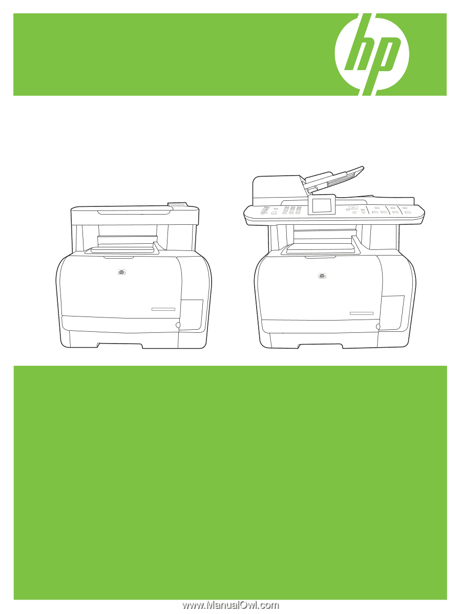
HP Color LaserJet CM1312 MFP Series
Service Manual