HP Dc7900 Technical Reference Guide: HP Compaq dc7900 Series Business Desktop - Page 60
Parallel Interface Connector, Table 5-5., DB-25 Parallel Connector Pinout
 |
UPC - 884962028483
View all HP Dc7900 manuals
Add to My Manuals
Save this manual to your list of manuals |
Page 60 highlights
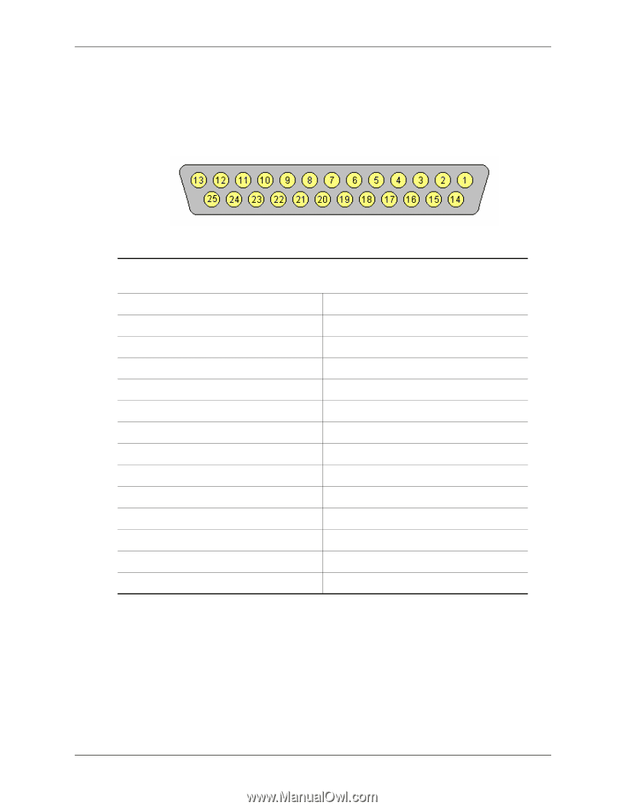
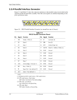
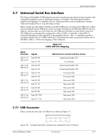
Input/Output Interfaces 5.5.4 Parallel Interface Connector Figure 5-5 and Table 5-5 show the connector and pinout of the parallel connector provided on the optional parallel bracket/cable assembly. Note that some signals are redefined depending on the port's operational mode. Figure 5-5. DB-25 Parallel Interface Connector (as viewed from rear of chassis) Table 5-5. DB-25 Parallel Connector Pinout Pin Signal Function 1 STB- Strobe / Write [1] 2 D0 Data 0 3 D1 Data 1 4 D2 Data 2 5 D3 Data 3 6 D4 Data 4 7 D5 Data 5 8 D6 Data 6 9 D7 Data 7 10 ACK- Acknowledge / Interrupt [1] 11 BSY Busy / Wait [1] 12 PE Paper End / User defined [1] 13 SLCT Select / User defined [1] Pin Signal Function 14 LF- Line Feed [2] 15 ERR- Error [3] 16 INIT- Initialize Paper [4] 17 SLCTIN- Select In / Address. Strobe [1] 18 GND Ground 19 GND Ground 20 GND Ground 21 GND Ground 22 GND Ground 23 GND Ground 24 GND Ground 25 GND Ground -- -- -- NOTES: [1] Standard and ECP mode function / EPP mode function [2] EPP mode function: Data Strobe ECP modes: Auto Feed or Host Acknowledge [3] EPP mode: user defined ECP modes:Fault or Peripheral Req. [4] EPP mode: Reset ECP modes: Initialize or Reverse Req. 5-8 www.hp.com Technical Reference Guide
-
 1
1 -
2
-
3
-
4
-
5
-
6
-
7
-
8
-
9
-
10
-
11
-
12
-
13
-
14
-
15
-
16
-
17
-
18
-
19
-
20
-
21
-
22
-
23
-
24
-
25
-
26
-
27
-
28
-
29
-
30
-
31
-
32
-
33
-
34
-
35
-
36
-
37
-
38
-
39
-
40
-
41
-
42
-
43
-
44
-
45
-
46
-
47
-
48
-
49
-
50
-
51
-
52
-
53
-
54
-
 55
55 -
 56
56 -
 57
57 -
 58
58 -
 59
59 -
 60
60 -
 61
61 -
 62
62 -
 63
63 -
 64
64 -
 65
65 -
66
-
67
-
68
-
69
-
70
-
71
-
72
-
73
-
74
-
75
-
76
-
77
-
78
-
79
-
80
-
81
-
82
-
83
-
84
-
85
-
86
-
87
-
88
-
89
-
90
-
91
-
92
-
93
-
94
-
95
-
96
-
97
-
98
-
99
-
100
-
101
-
102
-
103
-
104
-
105
-
106
-
107
-
108
-
109
-
110
-
111
-
112
-
113
-
114
-
115
-
116
-
117
-
118
-
119
-
120
 |
 |