HP Disk Carrier Blade for bh3710 Installation Guide, Second Edition - HP Carri - Page 42
Installing and Removing Blades With Locking Levers
 |
View all HP Disk Carrier Blade for bh3710 manuals
Add to My Manuals
Save this manual to your list of manuals |
Page 42 highlights
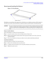
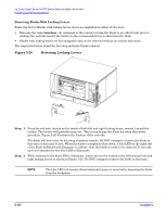
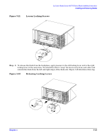
hp Carrier Grade Server bh3710 Server Blade Installation Information Installing and Removing Blades Installing and Removing Blades With Locking Levers Procedures for the installation and Removal of server blades with Locking Levers are listed and illustrated below. Installing Blades With Locking Levers Install the server blade according to the following steps: Step 1. Grasp the two locking levers and lift the blade from its antistatic surface. Step 2. If the locking levers are locked (levers do not open freely), press the red tabs on each locking lever in to unlock them. The open locking levers will then swing out with latches at right angles to the blade bulkhead. Step 3. Holding the blade by the locking levers, align it with the card guides inside the open slot and carefully push the blade fully into the chassis as shown in Figure 5-17. CAUTION Ensure that the locking levers are unlocked before seating the blade in the chassis and closing the locking levers. Failure to observe this precaution may cause the red tabs to break, thereby compromising air circulation. Figure 5-17 Align Blades With Card Guides and Push Into Chassis Step 4. When the blade is fully inserted, ensure that the hooks on the locking levers engage the chassis at the left and right edges of the blade slot. Step 5. Once the hooks engage the chassis, grasp the two locking levers and simultaneously push them toward each other to securely seat the blade in the connector on the backplane, as shown in the Figure 5-18. It may take additional effort to push the board into final seating, because it must mate with several connectors on the backplane. The red tabs on the inside of each locking lever will automatically click into position. Figure 5-18, shown below, illustrates the hooks engaging the chassis and the direction of force needed to close the locking levers. 5- 22 Chapter 5
-
 1
1 -
2
-
3
-
4
-
5
-
6
-
7
-
8
-
9
-
10
-
11
-
12
-
13
-
14
-
15
-
16
-
17
-
18
-
19
-
20
-
21
-
22
-
23
-
24
-
25
-
26
-
27
-
28
-
29
-
30
-
31
-
32
-
33
-
34
-
35
-
36
-
 37
37 -
 38
38 -
 39
39 -
 40
40 -
 41
41 -
 42
42 -
 43
43 -
 44
44 -
 45
45 -
 46
46 -
 47
47 -
48
-
49
-
50
-
51
-
52
-
53
-
54
-
55
 |
 |
