HP Disk System 2300 Power Supply Hardware Component Replacement Instructions - Page 2
Caution
 |
View all HP Disk System 2300 manuals
Add to My Manuals
Save this manual to your list of manuals |
Page 2 highlights
5 8 Pull the module from the slot. PORT 1 FC-AL 100MB/s A6214-60001 PORT 0 3 4 ADDRESS 5 LCC LINK 2 ACTIVE 6 LCC ACTIVE FC-AL 100MB/s 1 0 FAULT LINK ACTIVE PORT 1 FC-AL 100MB/s CAUTION DO NOT leave slot empty for more that 2 minutes. Push in both cam levers at the same time. 9 6 Pull out both levers on new module. 7 Push the module into the slot. Tighten the cam lever screws with a straight blade screwdriver. 10 Re-connect power cord. 11 Green LED indicates power supply is functioning.
-
 1
1 -
 2
2
 |
 |

10
11
7
8
9
5
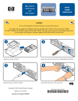
Pull the module from the slot.
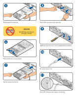
Push the module into the slot.
Pull out both levers on new module.
CAUTION
DO NOT leave slot empty for
more that 2 minutes.
6
Push in both cam levers at the same time.
Tighten the cam lever screws with a straight blade screwdriver.
Re-connect power cord.
Green LED indicates power supply is functioning.