HP Dv4-1124nr HP Pavilion dv4 Entertainment PC - Maintenance and Service Guide - Page 92
Disconnect the power from the computer by first unplugging the power cord from the AC outlet
 |
UPC - 884420609841
View all HP Dv4-1124nr manuals
Add to My Manuals
Save this manual to your list of manuals |
Page 92 highlights
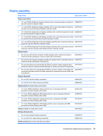
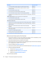
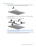
Description Spare part number ● For use with standard computer models with a camera/microphone module 486890-001 ● For use with bronze-colored Special Edition computer models with a camera/ microphone module 496734-001 ● For use with standard computer models 494967-001 ● For use with bronze-colored Special Edition computer models 496742-001 ● For use with standard computer models with Flush Glass display assemblies 486875-001 ● For use with bronze-colored Special Edition computer models with Flush Glass display 496733-001 assemblies Rubber display bezel kits (contains all rubber pieces for the display bezel) ● For use with standard computer models ● For use with bronze-colored Special Edition computer models 496729-001 486874-001 Miscellaneous display parts ● Hinge trim for use on standard computer models with Flush Glass display assemblies 495629-001 ● Hinge trim for use on bronze-colored Special Edition computer models with Flush Glass 502592-001 display assemblies ● Display trim for use with standard computer models with Flush Glass display assemblies 486877-001 ● Display trim for use with bronze-colored Special Edition computer models with Flush 502593-001 Glass display assemblies ● LCD cable for Flush Glass display assemblies 486878-001 ● Microphone cable for Flush Glass display assemblies 495631-001 ● LED transfer board for standard display assemblies 494977-001 Before removing the display assembly, follow these steps: 1. Shut down the computer. If you are unsure whether the computer is off or in Hibernation, turn the computer on, and then shut it down through the operating system. 2. Disconnect all external devices connected to the computer. 3. Disconnect the power from the computer by first unplugging the power cord from the AC outlet and then unplugging the AC adapter from the computer. 4. Remove the battery (see Battery on page 55). 5. Disconnect the wireless antenna cables from the WLAN module (see WLAN module on page 62). 6. Remove the following components: a. Keyboard (see Keyboard on page 72) b. Keyboard cover (see Keyboard cover on page 76) c. Speaker (see Speaker assembly on page 79) Remove the display assembly: 84 Chapter 4 Removal and replacement procedures
-
 1
1 -
2
-
3
-
4
-
5
-
6
-
7
-
8
-
9
-
10
-
11
-
12
-
13
-
14
-
15
-
16
-
17
-
18
-
19
-
20
-
21
-
22
-
23
-
24
-
25
-
26
-
27
-
28
-
29
-
30
-
31
-
32
-
33
-
34
-
35
-
36
-
37
-
38
-
39
-
40
-
41
-
42
-
43
-
44
-
45
-
46
-
47
-
48
-
49
-
50
-
51
-
52
-
53
-
54
-
55
-
56
-
57
-
58
-
59
-
60
-
61
-
62
-
63
-
64
-
65
-
66
-
67
-
68
-
69
-
70
-
71
-
72
-
73
-
74
-
75
-
76
-
77
-
78
-
79
-
80
-
81
-
82
-
83
-
84
-
85
-
86
-
 87
87 -
 88
88 -
 89
89 -
 90
90 -
 91
91 -
 92
92 -
 93
93 -
 94
94 -
 95
95 -
 96
96 -
 97
97 -
98
-
99
-
100
-
101
-
102
-
103
-
104
-
105
-
106
-
107
-
108
-
109
-
110
-
111
-
112
-
113
-
114
-
115
-
116
-
117
-
118
-
119
-
120
-
121
-
122
-
123
-
124
-
125
-
126
-
127
-
128
-
129
-
130
-
131
-
132
-
133
-
134
-
135
-
136
-
137
-
138
-
139
-
140
-
141
-
142
-
143
-
144
-
145
-
146
-
147
-
148
-
149
-
150
-
151
-
152
-
153
-
154
-
155
-
156
-
157
-
158
-
159
-
160
-
161
-
162
-
163
-
164
-
165
-
166
-
167
-
168
-
169
-
170
-
171
-
172
-
173
-
174
-
175
-
176
-
177
-
178
-
179
-
180
-
181
-
182
-
183
-
184
-
185
-
186
-
187
-
188
-
189
-
190
-
191
-
192
-
193
-
194
-
195
-
196
-
197
-
198
-
199
-
200
-
201
-
202
 |
 |
